
Research for Future Transportation System (Research for Scramjet Engine Flow Path)
JAXA Supercomputer System Annual Report April 2016-March 2017
Report Number: R16E0075
- Responsible Representative: Koichi Okita(Research and Development Directorate, Unit IV)
- Contact Information: Shigeru Sato(ssato@kakuda.jaxa.jp)
- Members: Shigeru Sato, Toshihiko Munakata, Masaaki Fukui, Masaharu Takahashi
- Subject Category: Space(Space transportation)
Abstract
As a future hypersonic propulsion engine scramjet engine has been studied in many countries including USA and others, and the research is widely spread from basic researches to flight tests. In our country the scramjet engine research has been carried out since the former National Aeronautical Laboratory in flight condition of Mach 4, 6 and 8 by utilizing Ramjet Engine Test Facility (RJTF) which was completed in 1993, and a lot of knowledge about the engine has been obtained. The factor that bothers engine performance completion has been found, and Sato et al are researching the solution by using CFD in order to create engine design method.
Goal
The purpose is to investigate the influence of the internal flow path on the engine performance by help of CFD in the viewpoint of aerodynamics about a scramjet engine which is a main mode of combined cycle propulsion engine as a reusable space propulsion engine, and to contribute to designing a combined cycle propulsion engine.
In other words it is to compare the engine results with CFD in order to extract effective factors on improvement of the engine performance from a lot of experimental results of engine tests stored in Kakuda Space Center, and to make CFD simulation about a trial engine configuration which is proposed for engine performance improvement.
Objective
In Kakuda Space Center, scramjet engine is being investigated as a main mode of combined cycle propulsion engine, and a lot of engine performance tests have been made by using Ramjet Engine Test Facility (RJTF). It has been found in the tests that the difference of engine inner configuration produces large difference of thrust performance in the flight condition of Mach 6. CFD simulations are being carried out based on the plenty of engine test data stored in Kakuda Space Center about how the difference of engine inner configuration of main elements of the engine, inlet, isolator, strut and others influent on the engine performance, and CFD simulations on trial engine configuration not yet tested are also carried out.
Aerodynamic effects of engine inner configuration are investigated by using CFD, compared with the engine tests, and systematized to prepare basis for decision for designing of combined cycle engine.
References and Links
N/A
Use of the Supercomputer
The supercomputer is utilized in order to carry out simulations of scramjet engine tests, and to apply the CFD based on the validation to engine configuration and to the flight condition which are not yet tested. By doing so, virtual test can be carried out on thesuper computer, and it will be possible to efficiently obtain the method for engine performance increase. And also this suggests the possibility that our country having the advantage of supercomputer performance can obtain leading results to other countries.
Necessity of the Supercomputer
Scramjet engine is still in developing stage, and there are many parameters on which engine performance depends. On the other hand, though engine tests are being carried out by utilizing engine test facility and element tests are also carried out by using element test facilities, experiments cannot cover all over the parameter range, for example Mach number range, and it will take huge hours and man power to build the engine technology. Therefore, it is necessary to use the supercomputer, to be based on the experimental results, to simulate the condition which cannot be realized in experiments, to recognize thermal-fluid dynamical phenomena in the working engine, to extract effective phenomena on the engine performance increase, and to make concepts from the extracted phenomena. Using of the supercomputer effectively promotes scramjet engine technology building.
Achievements of the Year
In order to compare to the result of engine configuration already tested in RJTF (Ramjet Engine Test Facility) located in Kakuda Space Center, a virtual engine test is being carried out about an improved engine configuration. The configurations has a boat-tail strut of which the tail is shortened and sharpened in order to improve the engine thrust performance, though it has the same basic dimension to the tested engine. Figure 1 shows the both configuration. The difference of engine inner quantity is compared between the both engine configurations. The comparison is done by investigating the influence of the shock waves in the condition of combustion in 3 dimension. Colored surface is the contour surface indicating the fuel H2 mass fraction of 0.05%, and the color distribution gives the temperature distribution of flow in the engine. Figure 2 shows the distributions. And then the colored contour lines seen in the engine exit are the mass flux (ρu) distribution of flow there in the combustion. In the comparison of the both engine configurations, it is common to the both that the fields around the 12 fuel injectors become red. The distinguishable, clear difference is the red distribution near the top wall in the nozzle section. This section is the place where the cowl shock comes in and reflects and the place where the combustion is encouraged. In the section the red area is bigger in the 5/5-Height Strut configuration. It is thought that the exothermic heat is bigger and the combustion is further encouraged corresponding to the color contour.
In the real engine tests, however, it has been observed that big heat released on the section increases the pressure on the top wall to cause the engine un-start (flow full separation on the top wall) easily.
Since deterring the engine un-start makes it possible to increase the fuel equivalence ratio and to contribute the engine performance extension, the design method is desirable in order to avoid the reaction heat concentration to the top wall side and to encourage the combustion in the middle of engine cross section. For example, in the case of side wall injection it will be found effective to close the injectors which bring the fuel to the top wall side and to open the selected injectors near the cowl.
At this moment the pressure value from CFD has underestimated, and the cause is being researched mainly in the view point of turbulence combustion model.
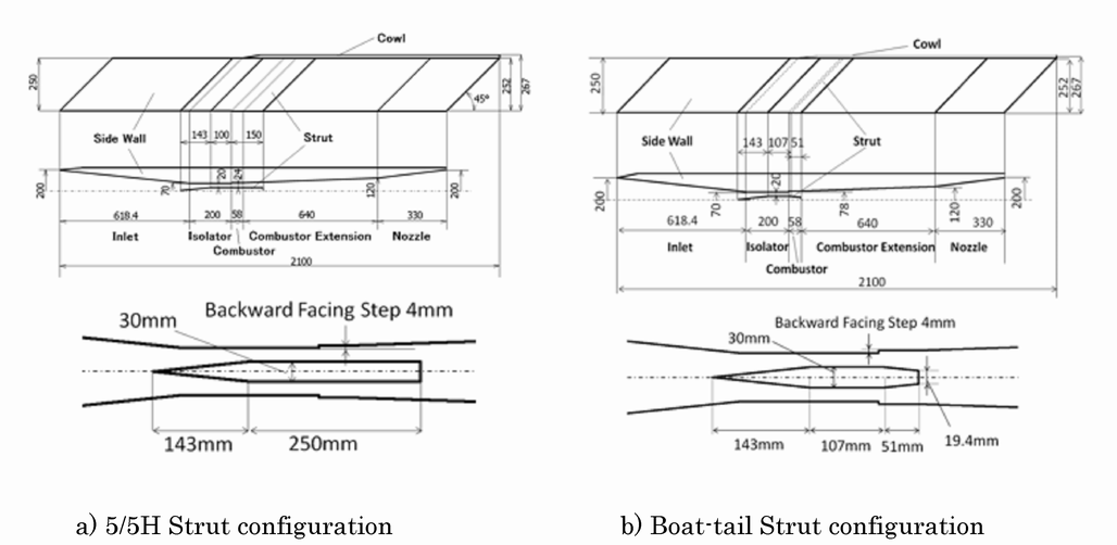
Fig.1:Two types of struts. The 5/5H Strut configuration (a) and the Boat-tail Strut configuration (b) are compared by means of CFD
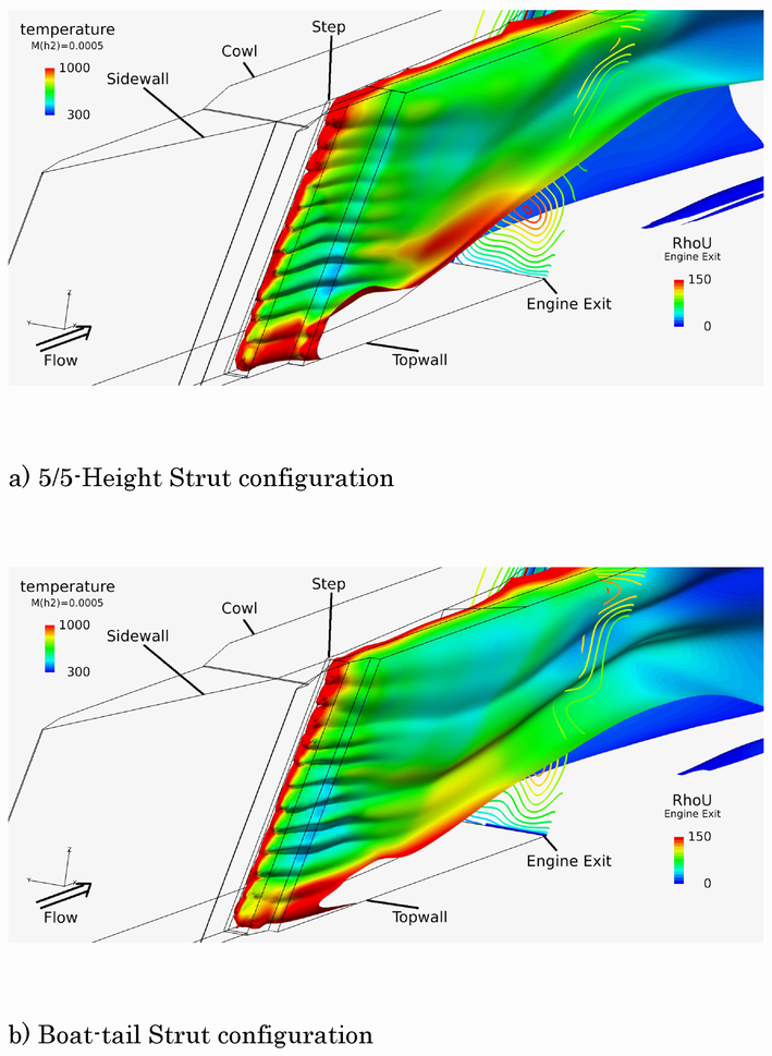
Fig.2:Trial combustion calculations in the both configurations – fuel injection and temperature distribution on 0.05% H2 mass concentration plain.
Publications
Non peer-reviewed articles
1) SATO Shigeru, FUKUI Masaaki, WATANABE Takahiro and MUNAKATA Toshihiko, A Consideration for Scramjet Engine Performance Improvement, Proceedings of the 48th Fluid Dynamic Conference/the 34th Aerospace Numerial Simulation Symposium, JAXA-SP-16-007, December 2016. (in Japanese)
Presentations
1) SATO Shigeru, FUKUI Masaaki, WATANABE Takahiro and MUNAKATA Toshihiko, A Consideration for Scramjet Engine Performance Improvement, the 48th Fluid Dynamic Conference/the 34th Aerospace Numerial Simulation Symposium, July 2016, Kanazawa. (in Japanese)
2) SATO Shigeru, Kimigaya, Kakuda-shi, FUKUI Masaaki, MUNAKATA Toshihiko, WATANABE Takahiro and TAKAHASHI Masaharu, A Trial for Scramjet Engine Performance Improvement - Preparing for Different Fuel Injections, Symposium on Shock Waves in Japan, March 2017, Yokosuka. (in Japanese)
Computational Information
- Parallelization Methods: Process Parallelization
- Process Parallelization Methods: MPI
- Thread Parallelization Methods: n/a
- Number of Processes: 4-8
- Number of Threads per Process: 1
- Number of Nodes Used: 1
- Elapsed Time per Case (Hours): 150
- Number of Cases: 10
Resources Used
Total Amount of Virtual Cost(Yen): 411,753
Breakdown List by Resources
| System Name | Amount of Core Time(core x hours) | Virtual Cost(Yen) |
|---|---|---|
| SORA-MA | 0.03 | 0 |
| SORA-PP | 45,196.63 | 385,889 |
| SORA-LM | 0.00 | 0 |
| SORA-TPP | 0.00 | 0 |
| File System Name | Storage assigned(GiB) | Virtual Cost(Yen) |
|---|---|---|
| /home | 39.07 | 368 |
| /data | 397.05 | 3,745 |
| /ltmp | 2,115.89 | 19,959 |
| Archiving System Name | Storage used(TiB) | Virtual Cost(Yen) |
|---|---|---|
| J-SPACE | 0.58 | 1,791 |
Note: Virtual Cost=amount of cost, using the unit price list of JAXA Facility Utilization program(2016)
JAXA Supercomputer System Annual Report April 2016-March 2017