
Investigation of Indirect Reynolds Number Effect
JAXA Supercomputer System Annual Report April 2019-March 2020
Report Number: R19EDA201N08
Subject Category: Aeronautical Technology
- Responsible Representative: Takashi Aoyama, Associate Senior Researcher, Aeronautical Technology Directorate, Numerial Simulation Research Unit
- Contact Information: Makoto Ueno, JAXA(ueno.makoto@jaxa.jp)
- Members: Wataru Yamazaki, Jun Sakamoto, Hiroki Ichihashi, Makoto Ueno
Abstract
This research analizes the influence of total pressure loss due to boundary layer tripping roughness on flow around an airplane wind tunnel model using computational fluid dynamics (CFD). It is objected to realize, especially, pressure distribution variation due to Reynolds number variation, which is known as the indirect effect.
Reference URL
N/A
Reasons and benefits of using JAXA Supercomputer System
It is necessary to perform CFD computation including flow around a whole aircraft because it requires highly parallelized computation. Additionally, the JSS2 was chosen because the FaSTAR CFD solver is optimized, as well.
Achievements of the Year
In airplane development, it is known that the equivalent flow around the airplane in flight is able to be reqlized even with a scaled wind tunnel model in the case of surrounding gas with the same specific heat ratio, the Mach number, and the Reynolds number, while it is very expensive to achieve such high Reynolds number as in flight, in wind tunnel tests. Usual wind tunnel tests are, therefore, performed in relatively low Reynolds number conditions in many cases, and the difference between the wind tunnel and the flight conditions sometimes brings severe aerodynamic problems in development. For example, the C-141 airlifter development program delayed due to shock wave position difference between wind tunnel test and flight test. This kind of catastrophic change with pressure distribution difference brought by Reynolds number effect is called as "indirect effect".
We have been performed CFD simulations for the flow around the C-141 to reproduce indirect effect by varying Reynolds numbers with little success. It is assumed in a literature that the shock wave position difference was caused by excessive loss due to the boundary layer transition roughness position located at too upstream than the ideal. To simulate this condition, artificial momentums loss are focibly placed in the boundary layer in the CFD simulation.
The computation was performed as 2-dimensional CFD simulation around the C-141 airfoil at the 38.9% half-span position. The momuntum was located at 5% downstream from the leading edge of the airfoil as the region which has a width of 0.1 chord length both in the x-, and the y-direction. The sign of the added momentum is negative for flow direction and positive for upward. The strength of the added momentum has a unit of N/m^3. As the result, it is shown that the artificial momentum loss addition in the boundary layer brings shock wave location displacement similar to the phenomenon of the C-141. The figure is shown in Fig.1.
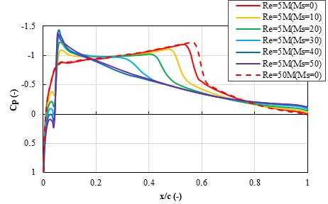
Fig.1: Cp distributions on the upper surface of C141 airfoil
Publications
- Non peer-reviewed papers
Jun Sakamoto, Hiroki Ichihashi, Wataru Yamazaki, Makoto Ueno, Investigation of Reynolds Number Effect of C-141 Aircraft, Seventeenth International Conference on Flow Dynamics, Sendai, Miyagi, Oct., 2020.
Hiroki ICHIHASHI, Wataru YAMAZAKI and Makoto UENO, Investigation of indirect Reynolds number effect around airfoil considering influence of roughness, JSME, Hokuriku Shin-etsu Branch, 57th Annual Meeting, Nagaoka, Niigata, Mar., 2020.
Usage of JSS2
Computational Information
- Process Parallelization Methods: MPI
- Thread Parallelization Methods: N/A
- Number of Processes: 216
- Elapsed Time per Case: 10 Hour(s)
Resources Used
Fraction of Usage in Total Resources*1(%): 0.39
Details
Please refer to System Configuration of JSS2 for the system configuration and major specifications of JSS2.
| System Name | Amount of Core Time(core x hours) | Fraction of Usage*2(%) |
|---|---|---|
| SORA-MA | 3,507,969.12 | 0.43 |
| SORA-PP | 0.00 | 0.00 |
| SORA-LM | 0.00 | 0.00 |
| SORA-TPP | 0.00 | 0.00 |
| File System Name | Storage Assigned(GiB) | Fraction of Usage*2(%) |
|---|---|---|
| /home | 9.54 | 0.01 |
| /data | 95.37 | 0.00 |
| /ltmp | 1,953.13 | 0.17 |
| Archiver Name | Storage Used(TiB) | Fraction of Usage*2(%) |
|---|---|---|
| J-SPACE | 0.00 | 0.00 |
*1: Fraction of Usage in Total Resources: Weighted average of three resource types (Computing, File System, and Archiver).
*2: Fraction of Usage:Percentage of usage relative to each resource used in one year.
JAXA Supercomputer System Annual Report April 2019-March 2020