Numerical Study on Rotor Performance of Mars Helicopter
JAXA Supercomputer System Annual Report April 2019-March 2020
Report Number: R19EACA41
Subject Category: JSS2 Inter-University Research
- Responsible Representative: Makoto Sato, Associate Professor, Kogakuin University
- Contact Information: Makoto Sato, Kogakuin University(msato@cc.kogakuin.ac.jp)
- Members: Makoto Sato, Daichi Ogasawara
Abstract
Mars helicopter project is now going. Since the atomospheric density on Mars is about 1/100, the sound of speed is about 3/4 compared with those on Earth, we need to develop the high perfmance heli-rotar. In JAXA, the experimental measurements of the heli-rotar performance at low-Reynolds number condition have been conducted. In the present research, we conduct numerical simulations on the rotational flat-plate-airfoil flow in order to clarify the characteristics of the flow field.
Reference URL
N/A
Reasons and benefits of using JAXA Supercomputer System
We need to conduct the large-scale simulations on the rotational wing flow using “rFlow3D”, which has been developed in JAXA.
Achievements of the Year
We have conducted the numerical simulation on the rotational flat-plate-airfoil flow. The computational object and conditions are decided based on the experiments at Tohoku University[1]. The computational parameters are the Reynolds number(7380-73800), pitch angle(0-30) and aspect ratio(2-4). Here, the results of AR=4 cases are shown. The flow solver is rFLow3D, which has been developed at JAXA.
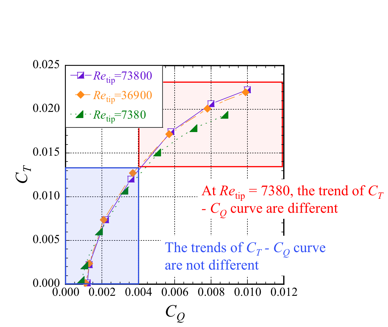
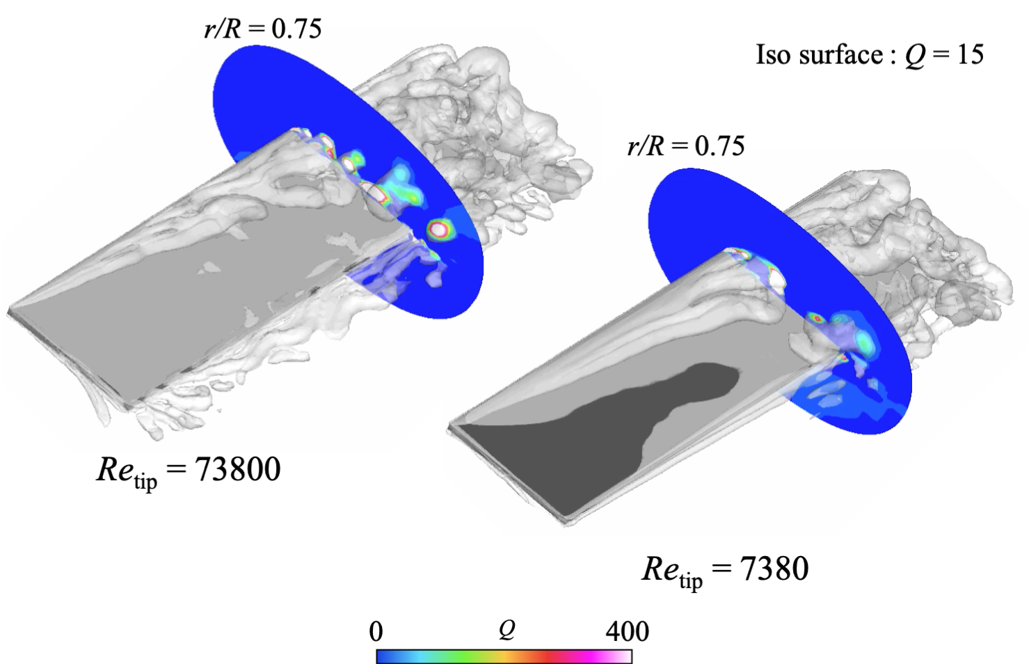
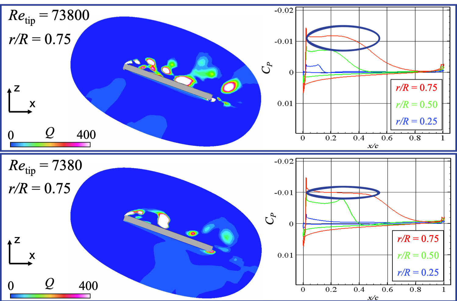
Figure 1 shows Ct(thrust coefficient)-Cq(torque coefficient) curves. For the cases with low pitch angles, the trend of Ct-Cq curves is alomost the same. On the other hand, For the cases with high pitch angles, Ct-Cq curve of Re=7380 shows different trend from other cases. Figure 2 shows vortex structures around flat-plate-airfoil for the case with Re=7380, 73800 and pitch angle 20 degrees. The sequential sheddings of leading-edge vortices and their convections can be observed for the case of Re=73800. On the other hand, the relatively large-scale separation vortex is shed from the leading-edge. Figure 3 shows the vortex structures on the cross sections and Cp distributions. From the comparison between the case of Re=7380 and Re=73800, it can be said that the region of the flat Cp becomes larger in Re=7380 than that in Re=73800. This is because the large-scale separation vortex from the leading-edge results in the large reverse flow region above the airfoil in Re=7380.
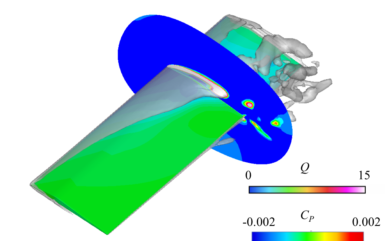
In addition to the rotational flat-plate-airfoil, now we are conducting the simulation on the “triangle-airfoil”. Figure 4 shows the vortex structure around the rotational triangle-airfoil. The separation vortex is clearly different from that of the flat-plate-airfoil. The detailed analysis will be conducted soon.
[1] Okoucuhi, M. “Experimental research on aero-characteristics of rotar at low-Reynolds numer condition”, Master Thesis of Tohoku University, (2013).
Publications
– Oral Presentations
D. Ogasawara, M. Sato, H. Sugawara, Y. Tanabe, “Numerical simulation of a rotating blade using a flat-plate airfoil at low Reynolds numbers for Mars helicopter”, 72nd Annual Meeting of the American Physical Society Division of Fluid Dynamics
Usage of JSS2
Computational Information
- Process Parallelization Methods: N/A
- Thread Parallelization Methods: OpenMP
- Number of Processes: 1
- Elapsed Time per Case: 400 Hour(s)
Resources Used
Fraction of Usage in Total Resources*1(%): 0.18
Details
Please refer to System Configuration of JSS2 for the system configuration and major specifications of JSS2.
| System Name | Amount of Core Time(core x hours) | Fraction of Usage*2(%) |
|---|---|---|
| SORA-MA | 0.00 | 0.00 |
| SORA-PP | 469,490.28 | 3.04 |
| SORA-LM | 0.00 | 0.00 |
| SORA-TPP | 0.00 | 0.00 |
| File System Name | Storage Assigned(GiB) | Fraction of Usage*2(%) |
|---|---|---|
| /home | 19.07 | 0.02 |
| /data | 19,531.26 | 0.33 |
| /ltmp | 3,906.25 | 0.33 |
| Archiver Name | Storage Used(TiB) | Fraction of Usage*2(%) |
|---|---|---|
| J-SPACE | 0.00 | 0.00 |
*1: Fraction of Usage in Total Resources: Weighted average of three resource types (Computing, File System, and Archiver).
*2: Fraction of Usage:Percentage of usage relative to each resource used in one year.
JAXA Supercomputer System Annual Report April 2019-March 2020

