Combustion analysis technology
JAXA Supercomputer System Annual Report April 2018-March 2019
Report Number: R18EG3212
Subject Category: Research and Development
- Responsible Representative: Eiji Shima, Director, Research and Development Directorate, Research Unit III
- Contact Information: Takanori Haga, Research and Development Directorate, Research Unit III(haga.takanori@jaxa.jp)
- Members: Takayuki Ito, Ryoji Takaki, Seiji Tsutsumi, Hiroyuki Ito, Taro Shimizu, Junya Aono, Takanori Haga, Yuhi Morii, Masaharu Abe, Masayuki Kakehi, Mikiroh Motoe, Manabu Hisida, Hideyo Negishi, Yoichi Ohnishi, Miki Nishimoto, Yu Daimon, Ashvin Hosangadi, Masaaki Ino, Osamu Fukasawa, Shinji Ohno, Andrea Zambon, Takenori Nakajima, Takashi Amemiya, Yutaka Umemura, Hironori Fujiwara, Hiroumi Tani, Keiichiro Fujimoto, Tetsufumi Ohmaru, Akiko Kotani, Taroh Fukuda, Mayu Matsumoto, Masashi Toyama, Kei Nishimura, Daiki Muto, Nozomu Kanno, Takeshi Watanabe
Abstract
To capture the unsteady phenomena in the liquid rocket engine, combustion large eddy simulations (LES) are carried out, and this evaluation tool is validated by comparing with a sub-scale test.
Reference URL
Please refer to ‘Research on software, computational engineering, and verification technology | JAXA|Research and Development Directorate‘.
Reasons for using JSS2
Since the flow and combustion in rocket chambers are in a turbulent state and have nonstationary characteristics, LES analysis is essential. Even in this verification target, analysis calculation of about several million steps is required for grid of tens of millions of cells, so it is impossible to achieve the target without using supercomputer.
Achievements of the Year
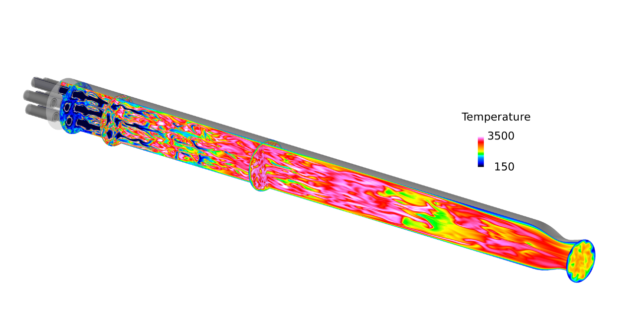
1. Towards the improvement of reacting flow simulations, Large eddy simulation of a methane/oxygen multi-element subscale combustion chamber is performed. JAXA/JEDI in-house CFD solver LS-FLOW is used in the present simulation. For combustion modeling, the laminar flamelet approach is applied. The number of grid point is approximately 0.24 billion. Figure 1 shows the instantaneous temperature contour. The present simulation captures the complex turbulent combustion field including mixing and combustion, and subsequent flame interaction structures.
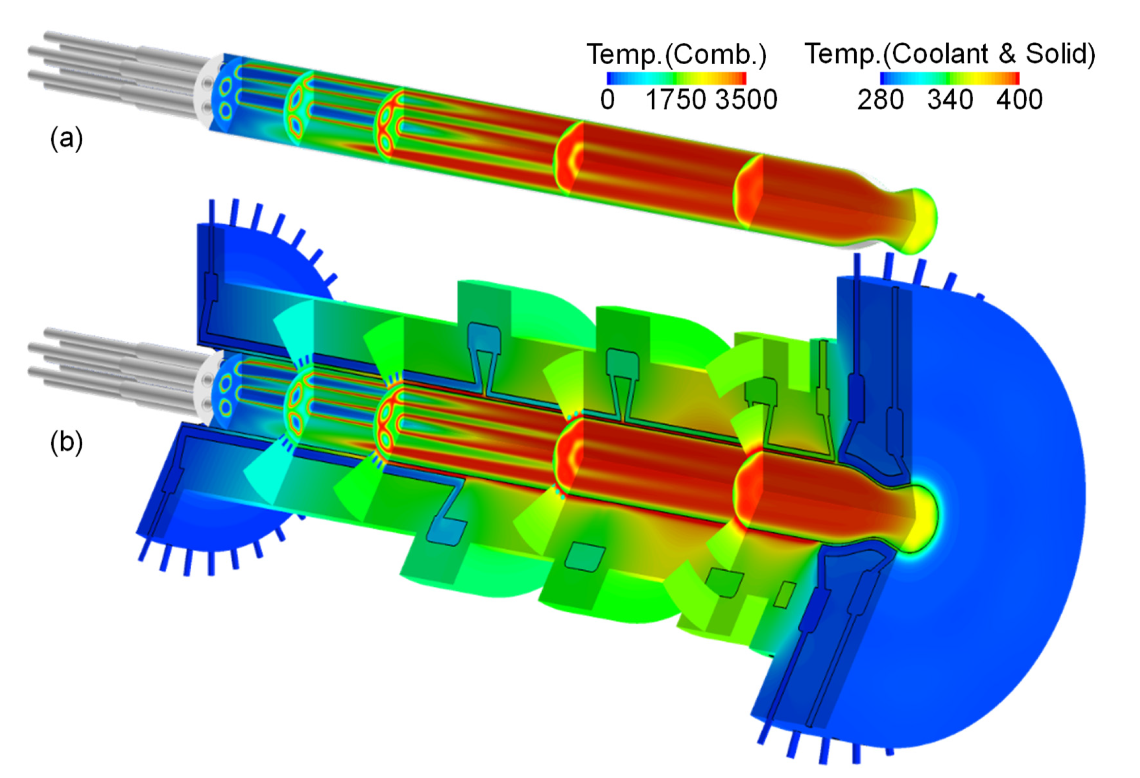
2. A fully conjugated combustion and heat transfer simulation was performed and validated for GCH4/GO2 combustion with a water-cooled calorimeter chamber. The employed numerical methodology was based on the three-dimensional Reynolds-averaged Navier-Stokes simulation in which the injection and combustion processes of propellants on the hot-gas side, heat conduction in the chamber wall, and cooling channel flows were considered. Figure 2 shows the temperature distributions of the (a) non-coupled and (b) coupled simulation results. In the combustion chamber, the high temperature region, which corresponds to the diffusion flame, extends gradually. The low temperature region, which corresponds to the GOX core, narrows gradually. The heat of combustion gas is transferred to the wall, then conducted through the chamber wall and then into the cooling water in the rectangular and circular tubes.
Publications
– Non peer-reviewed papers
1) Daiki Muto, Yu Daimon, Taro Shimizu, and Hideyo Negishi, A wall model including chemical effects for predicting wall heat transfer in combustion chambers, 56th Symposium (Japanese) on Combustion, B331, 2018 (in Japanese).
2) Daiki Muto, Yu Daimon, Taro Shimizu, and Hideyo Negishi, Wall modeling of reacting turbulent flow and heat transfer in liquid rocket engines, 2018 Joint Propulsion Conference, AIAA Propulsion and Energy Forum, AIAA 2018-4870, 2018.
3) Daiki Muto, Yu Daimon, Taro Shimizu, and Hideyo Negishi, Wall-modeled large eddy simulations of turbulent heat transfer at supercritical pressures, 55th National Heat Transfer Symposium of Japan, J322, 2018 (in Japanese).
4) Yu Daimon, Hideyo Negishi, Simona Silvestri, Oskar J. Haidn, “Conjugated Combustion and Heat Transfer Simulation for a 7 element GOX/GCH4 Rocket Combustor,” AIAA 2018-4553, Joint Propulsion Conference, 2018
Usage of JSS2
Computational Information
- Process Parallelization Methods: MPI
- Thread Parallelization Methods: N/A
- Number of Processes: 3200 – 6400
- Elapsed Time per Case: 1500 Hour(s)
Resources Used
Fraction of Usage in Total Resources*1(%): 5.46
Details
Please refer to System Configuration of JSS2 for the system configuration and major specifications of JSS2.
| System Name | Amount of Core Time(core x hours) | Fraction of Usage*2(%) |
|---|---|---|
| SORA-MA | 49,699,070.75 | 6.08 |
| SORA-PP | 71,716.79 | 0.57 |
| SORA-LM | 5,147.93 | 2.40 |
| SORA-TPP | 16,237.54 | 1.19 |
| File System Name | Storage Assigned(GiB) | Fraction of Usage*2(%) |
|---|---|---|
| /home | 5,896.12 | 6.10 |
| /data | 114,509.95 | 2.02 |
| /ltmp | 19,865.96 | 1.70 |
| Archiver Name | Storage Used(TiB) | Fraction of Usage*2(%) |
|---|---|---|
| J-SPACE | 119.91 | 4.20 |
*1: Fraction of Usage in Total Resources: Weighted average of three resource types (Computing, File System, and Archiver).
*2: Fraction of Usage:Percentage of usage relative to each resource used in one year.
JAXA Supercomputer System Annual Report April 2018-March 2019


