
Research for Future Transportation System (Research for Scramjet Engine Flow Path)
JAXA Supercomputer System Annual Report April 2018-March 2019
Report Number: R18EG3104
Subject Category: Research and Development
- Responsible Representative: Shigeru Sato, Researcher, Research Unit 4, Research and Development Directorate
- Contact Information: Shigeru Sato, Researcher, Research Unit 4, Research and Development Directorate (sato.shigeru@jaxa.jp)
- Members: Shigeru Sato, Toshihiko Munakata, Masaaki Fukui, Masaharu Takahashi
Abstract
The purpose is to investigate the influence of the internal flow path on the engine performance by help of CFD in the viewpoint of aerodynamics about a scramjet engine as a reusable space propulsion engine, and to contribute to designing a scramjet engine.
In other words it is to compare the engine results with CFD in order to extract effective factors on improvement of the engine performance from a lot of experimental results of engine tests stored in Kakuda Space Center, and to make CFD simulation about a trial engine configuration which is proposed for engine performance improvement.
Reference URL
Please refer to 'JAXA Repository / AIREX: スクラムジェットエンジン性能向上に関する試み —燃焼状態下の衝撃波'.
Reasons for using JSS2
In Kakuda Space Center, scramjet engine is being investigated, and a lot of engine performance tests have been made by using Ramjet Engine Test Facility (RJTF). It has been found in the tests that the difference of engine inner configuration produces large difference of thrust performance in the flight condition of Mach 6. CFD simulations are being carried out based on the plenty of engine test data stored in Kakuda Space Center about how the difference of engine inner configuration of main elements of the engine, inlet, isolator, strut and others influent on the engine performance, and CFD simulations on trial engine configuration not yet tested are also carried out.
Aerodynamic effects of engine inner configuration are investigated by using CFD, compared with the engine tests, and systematized to prepare basis for decision for designing of scramjet engines.
Achievements of the Year
In order to compare to the result of engine configuration already tested in RJTF (Ramjet Engine Test Facility) located in Kakuda Space Center, a virtual engine test is being carried out about an improved engine configuration. The configuration has a boat-tail strut of which the tail is shortened and narrowed in order to improve the engine thrust performance, though it has the same basic dimension to the tested engine. Figure 1 shows the tested engine outline. Figure 2 shows the difference of engine inner quantity in the both engine configurations.
A commercial code ANSYS Fluent is applied to this calculation, and structured grid system is used. The minimum grid size is set by 0.1mm near the cowl leading edge. The calculation is done in the half of the engine model assuming mirror condition in the engine symmetric center plane. The number of grids at the maximum is 5.03x10⁶. The limiter is the second order accuracy, space integral is AUSM+, time integral is explicit method, and turbulence model is k-omega model. For the combustion calculation, a model used here is the model of Fluent including Hydrogen-Oxygen reaction equation based on the Petersen and Hanson.*) This time Finite Rate Chemistry Model is employed for the combustion calculation, and the reaction consists of 9 species and 20 elementary reactions.
Engine air flow condition for calculation is set at Mach 5.3 in the engine entrance, and total temperature is set at 1500K. RJTF nozzle exit boundary layer (57.9mm thickness / 99.9% of main stream velocity) is also set in the flows into the engine, which corresponds to the boundary layer on the air frame bottom surface.
The calculation is performed mainly on JAXA's present Supercomputer System the 2nd Generation,JSS2. It is used remotely from Kakuda Space Center.
Figure 3 gives the equivalence rato distributions in combustion flow. Fig.3a shows the 5/5-Height strut configuration, and Fig.3b shows the Boat-tail strut configuration. The both are the equvalence ratio contours in the engine exit. In the 5/5-Height strut configuration the equivalence ratio distribution is almost simulated, but protrusions are left in the both corners close to the tap wall along the both side walls showing higher value than the expeimental value. On the other hand, in the boat-tail strut configuration the equivalence ratio much more spreads, and the equivalence ratio more than 1.0 is hardly seen. In the comparison, it is confirmed that the boat tail strut configuration relatively has an effect of spreading the fuel in the engine cross section.
Figure 4 gives the combustion efficiency distributions oppositely to the above. Fig.4a shows the 5/5-Height strut configuration, and Fig.4b shows the Boat-tail strut configuration. The both are the combustion efficiency distribution at the engine exit. The efficiency less than 0.8 is seen in the middle of the engine cross section, which is not seen in the RJTF experimant result. On the other hand, in the boat-tail strut configuration the high combusiton efficiency is seen allover the engine cross section due to the equivalence ratio spread. In the CFD comparison the boat tail strut configuraton will show better performance.
It is needed to research the engine inner flow by increasing the CFD accuracy and to find origins of thrust product. Finding the origins will make it possible to build methods to create the engine performance.
*)Petersen, E.L. and Hanson, R.K., Journal of Propulsion & Power, Vol. 15, No. 4, July-August 1999.
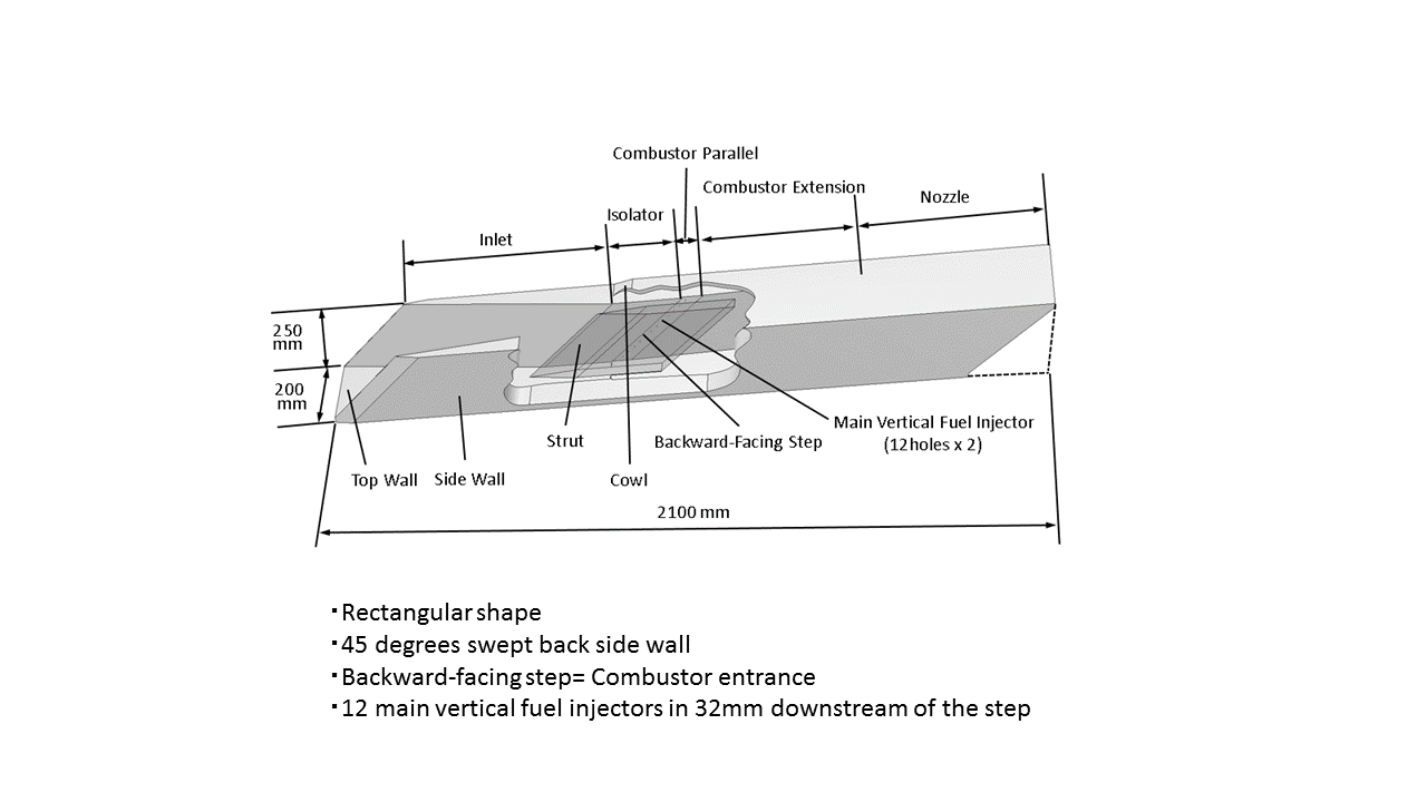
Fig.1: Outline of scramjet engine tested. The engine is set upside-down on the test bed, and 5/5-hieght strut is equipped.
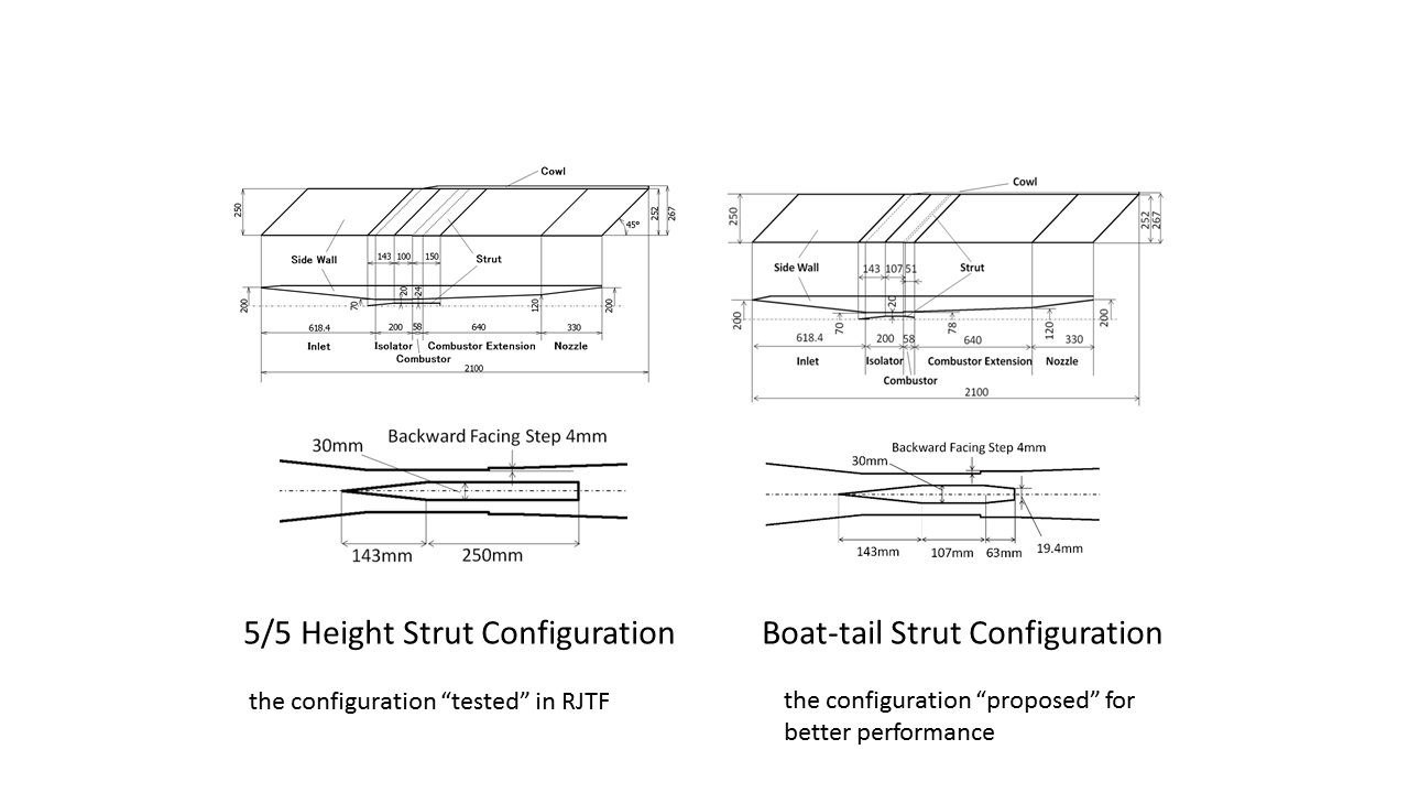
Fig.2: Two types of strut for CFD comparison. a) 5/5H-Strut configuration is used in engine test, and b) the Boat-tail Strut configuration is an improved one designed as a virtual configuration. (unit:mm)
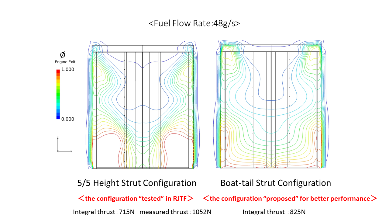
Fig.3: Calculated equivalence ratio phi distribution at the engine exit in the combustion flow.
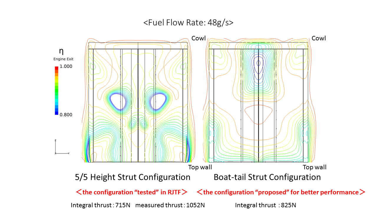
Fig.4: Calculated combustion efficiency eta distribution at the engine exit in the combustion flow.
Publications
- Non peer-reviewed papers
1)Shigeru SATO, Masaaki FUKUI, Takahiro Watanabe, Masaharu Takahashi and Toshihiko MUNAKATA, Shock Wave in Combustion in a Scramjet Engine, AIAA2019-0678, AIAA Science and Technology Forum and Exposition (AIAA SciTech 2019), January, 2019, San Diego.
Usage of JSS2
Computational Information
- Process Parallelization Methods: It depends on FLUENT
- Thread Parallelization Methods: It depends on FLUENT
- Number of Processes: 4 - 8
- Elapsed Time per Case: 720 Hour(s)
Resources Used
Fraction of Usage in Total Resources*1(%): 0.00
Details
Please refer to System Configuration of JSS2 for the system configuration and major specifications of JSS2.
| System Name | Amount of Core Time(core x hours) | Fraction of Usage*2(%) |
|---|---|---|
| SORA-MA | 0.00 | 0.00 |
| SORA-PP | 0.00 | 0.00 |
| SORA-LM | 7.38 | 0.00 |
| SORA-TPP | 0.00 | 0.00 |
| File System Name | Storage Assigned(GiB) | Fraction of Usage*2(%) |
|---|---|---|
| /home | 24.25 | 0.03 |
| /data | 246.18 | 0.00 |
| /ltmp | 1,432.29 | 0.12 |
| Archiver Name | Storage Used(TiB) | Fraction of Usage*2(%) |
|---|---|---|
| J-SPACE | 0.36 | 0.01 |
*1: Fraction of Usage in Total Resources: Weighted average of three resource types (Computing, File System, and Archiver).
*2: Fraction of Usage:Percentage of usage relative to each resource used in one year.
JAXA Supercomputer System Annual Report April 2018-March 2019