
Investigation of internal flow of aircraft combustor for En-Core Project.
JAXA Supercomputer System Annual Report April 2018-March 2019
Report Number: R18EA0714
Subject Category: Aeronautical Technology
- Responsible Representative: Mitsumasa Makida(JAXA, Aeronautical Technology Directorate)
- Contact Information: Mitsumasa Makida(JAXA, Aeronautical Technology Directorate)(makida.mitsumasa@jaxa.jp)
- Members: Mitsumasa Makida, Naoki Nakamura, Takashi Ishiyama
Abstract
In the development process of aircraft combustors, air mass flow distribution between fuel nozzles, dilution and cooling air holes on the liner effects performances of combustors. So it is important to understand the internal flow and estimate the mass flow distribution. In this research, we conduct cold-flow simulations of internal flow inside the combustor which faithfully simulates the configuration of practical combustor. Then we aim to develop methods to analyze aerodynamic performance of combustors such as air mass flow distribution with high accuracy.
Reference URL
N/A
Reasons for using JSS2
It is important to do parametric case study with slightly different geometry, and each case needs large scale simulation. To conduct such simulation effectively, we need the super computer with high parallelization efficiency.
Achievements of the Year
In this fiscal year, we conducted cold-flow simulations for a single-sector combustor. These simulations aimed to estimate the effect of the angle of conical heat shield on the internal flow of the combustor. Fig.1 shows the calculation girds and boundary conditions and Fig.2 shows stream lines from the pilot fuel nozzle for the heat shield angle of 45 degree. The calculation region starts from the inlet of the pressure-resistant casing to the outlet of the combustor. Calculations were also conducted for the angle of 50, 55 and 60 degree cases. To do parametric studies by changing minimum parts of combustor configuration, the overset boundary method, in which corresponding parts can be changed, is effective.
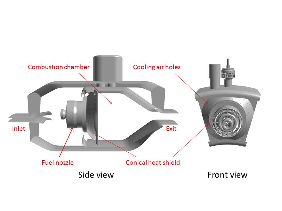
Fig.1: Total view of combustor
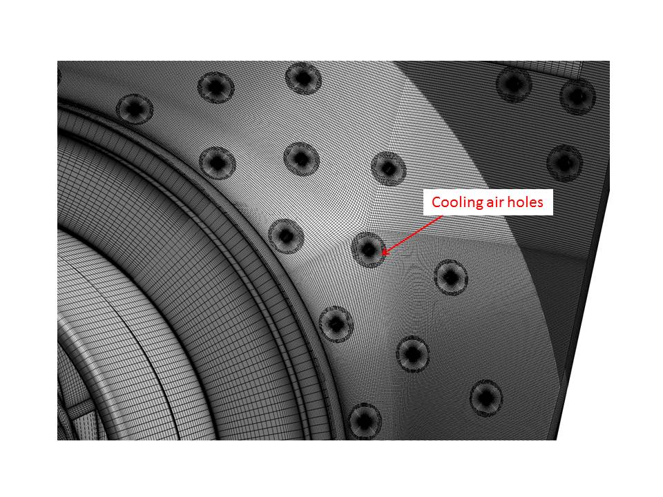
Fig.2: Calculation grids near cooling air holes
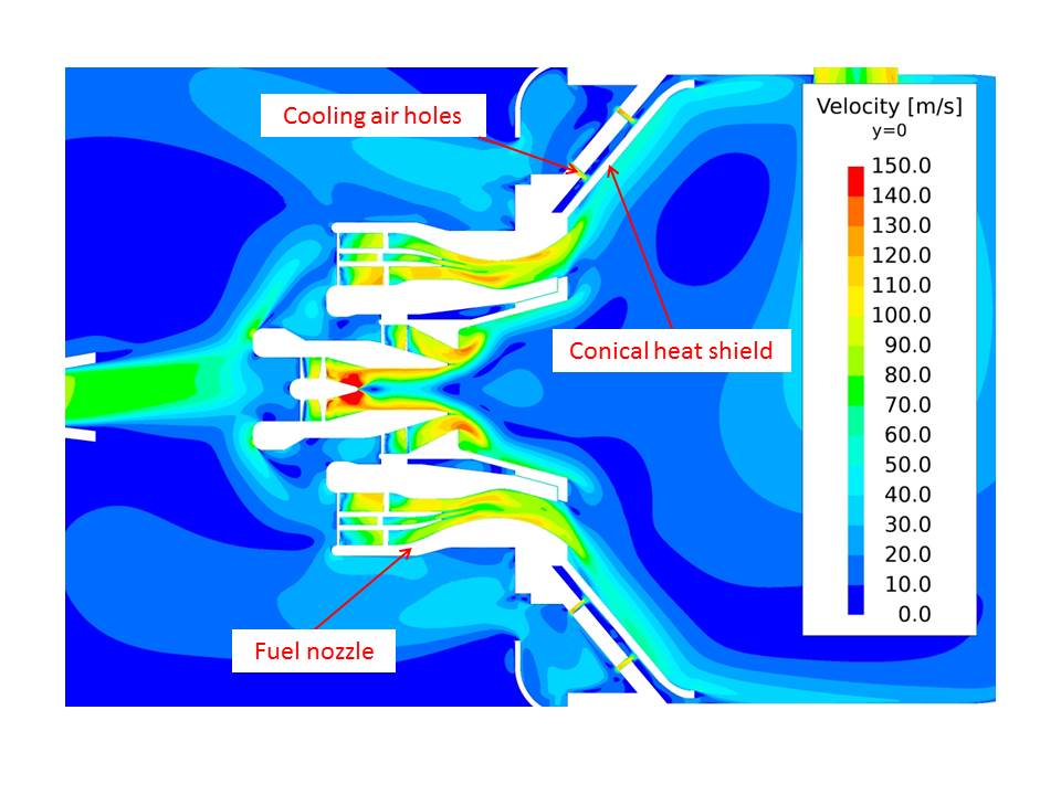
Fig.3: Velocity contour near fuel nozzle
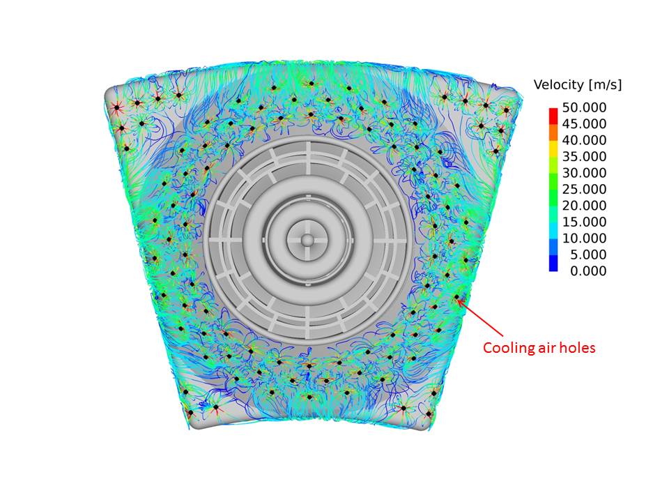
Fig.4: Stream lines from cooling air holes behind conical heat shield
Publications
N/A
Usage of JSS2
Computational Information
- Process Parallelization Methods: MPI
- Thread Parallelization Methods: Automatic Parallelization
- Number of Processes: 64
- Elapsed Time per Case: 250 Hour(s)
Resources Used
Fraction of Usage in Total Resources*1(%): 0.21
Details
Please refer to System Configuration of JSS2 for the system configuration and major specifications of JSS2.
| System Name | Amount of Core Time(core x hours) | Fraction of Usage*2(%) |
|---|---|---|
| SORA-MA | 1,839,236.91 | 0.23 |
| SORA-PP | 17,831.17 | 0.14 |
| SORA-LM | 0.00 | 0.00 |
| SORA-TPP | 0.00 | 0.00 |
| File System Name | Storage Assigned(GiB) | Fraction of Usage*2(%) |
|---|---|---|
| /home | 82.81 | 0.09 |
| /data | 7,402.33 | 0.13 |
| /ltmp | 1,450.89 | 0.12 |
| Archiver Name | Storage Used(TiB) | Fraction of Usage*2(%) |
|---|---|---|
| J-SPACE | 1.85 | 0.06 |
*1: Fraction of Usage in Total Resources: Weighted average of three resource types (Computing, File System, and Archiver).
*2: Fraction of Usage:Percentage of usage relative to each resource used in one year.
JAXA Supercomputer System Annual Report April 2018-March 2019