
Numerical Study of Hypersonic Intake
JAXA Supercomputer System Annual Report April 2017-March 2018
Report Number: R17ETET10
Subject Category: Skills Acquisition System
- Responsible Representative: Takashi Aoyama, Aeronautical Technology Directorate, Numerical Simulation Research Unit
- Contact Information: Atsushi Hashimoto hashimoto.atsushi@jaxa.jp
- Members: Tsukasa Nagao, Hidekazu Yoshida, Masakazu Sano
Abstract
JAXA is developing a hypersonic turbojet which work at less than Mach 1 to Mach 5. The intake of the hypersonic turbojet reduces air speed and compresses air. We conducted the CFD analysis to understand these flow field and operating conditions and develop a higher efficiency hypersonic turbojet.
Reference URL
Please refer to 'Hypersonic passenger aircraft technology | Sky Frontier – Sky Frontier Program | Aeronautical Technology Directorate'.
Reasons for using JSS2
We need to calculate about 30 unsteady or steady three dimensional models to investigate the performance of the inlet for High Mach Integrated Control experiment. We use fast flow solver FaSTAR developed by JAXA for the CFD analysis.
Achievements of the Year
The inlet for HIgh Mach Integrated COntrol experiment; HIMICO has a variable geometry inlet and the height of inlet throat can be changed by moving the 2nd and 3rd ramps. The inlet has a clearance between the 2nd or 3rd ramps and the side wall to avoid interference between them. We call this side-clearance and define the width of side-clearance as wside. Numerical simulation has been conducted to investigate the side-clearance effect on the Inlet performance of HIMICO by comparing several cases each of which has different wside.
(Fig.1) and (fig.2) show Mach number contours along the center line (Upper) and the line 16.5 mm away from the center line (Lower). (Fig.1) is the case at the nozzle height =13 mm and (fig.2) is the case at the nozzle height=9 mm. From (fig.1), we can see that a large flow separation at the 2nd ramp occurs only when wside=1 mm at the center line. On the other hand, it occurs when wside=0.5 mm, 0.75 mm, and 1 mm nearby the side wall and a oblique shock from the 2nd ramp leaks to out of the inlet. From (fig.2), we can see the same flow separation when wside=0.5 mm, 0.75 mm, and 1 mm at the center line.
(Fig.3) shows performance maps each wside. The performance map of the case wside=1 mm agrees with EFD results within 5% errors of mass capture ratio; MCR and that of the case wside=0 mm agrees with theoretical value within 2% errors of MCR. From these results we concluded that the cause of the MCR difference between EFD results and theoretical value is the side-clearance and the leaking to out of the inlet of an oblique shock from 2nd ramp causes the MCR reduction of EFD results compared with theoretical value.
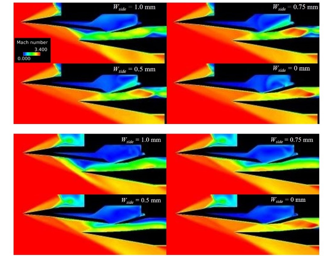
Fig.1: Mach Number Contour along center line (Upper) and nearby the side wall (Lower) at height of nozzle= 13 mm
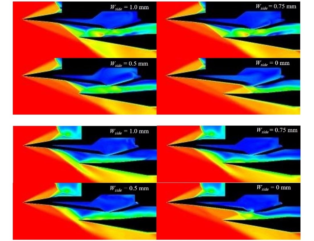
Fig.2: Mach Number Contour along center line (Upper) and nearby the side wall (Lower) at height of nozzle= 9 mm
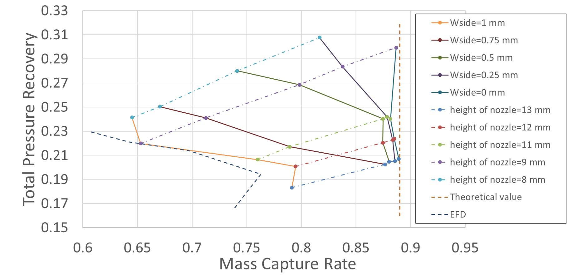
Fig.3: Performance map
Publications
■ Peer-reviewed papers
1)Nagao, T., et al.,"Numerical analysis on Supersonic Inlet Buzz",The Japan Society for Aeronautical and Space Science (submitted)
■ Presentations
1)Yoshida,H., et al.,"Numerical Study of Hypersonic Air Intake Aerodynamics Performance for High Mach Integrated Control Experiment "HIMICO"", AIAA Propulsion and Energy Forum 2017
2)Yoshida,H., et al.,"Numerical Study of Inlet Buzz Prediction for the Silent Supersonic Transport", 55th Aircraft Symposium
3)SANO, M., et al.,"Influence of the side clearance on the inlet for Hi-Mach Integrated Control Experiment (HIMICO)", Space Transportation Symposium FY2017
4)Yoshida, H., et al.,"Numerical Study of Inlet Performance with Airframe/Propulsion Interference for High Mach Integrated Control Experiment "HIMICO"", AJCPP2018
5)SANO, M., et al.,"Numerical Analysis of Supersonic Air-Intake Buzz", Aerospace Fluid Science Summer School 2017
Usage of JSS2
Computational Information
- Process Parallelization Methods: MPI
- Thread Parallelization Methods: N/A
- Number of Processes: 512 - 1024
- Elapsed Time per Case: 12.00 hours
Resources Used
Fraction of Usage in Total Resources*1(%): 0.93
Details
Please refer to System Configuration of JSS2 for the system configuration and major specifications of JSS2.
| System Name | Amount of Core Time(core x hours) | Fraction of Usage*2(%) |
|---|---|---|
| SORA-MA | 7,438,629.22 | 0.99 |
| SORA-PP | 26,731.96 | 0.33 |
| SORA-LM | 2,995.19 | 1.54 |
| SORA-TPP | 0.00 | 0.00 |
| File System Name | Storage Assigned(GiB) | Fraction of Usage*2(%) |
|---|---|---|
| /home | 495.91 | 0.34 |
| /data | 29,296.89 | 0.54 |
| /ltmp | 5,859.38 | 0.44 |
| Archiver Name | Storage Used(TiB) | Fraction of Usage*2(%) |
|---|---|---|
| J-SPACE | 3.56 | 0.15 |
*1: Fraction of Usage in Total Resources: Weighted average of three resource types (Computing, File System, and Archiver).
*2: Fraction of Usage:Percentage of usage relative to each resource used in one year.
JAXA Supercomputer System Annual Report April 2017-March 2018