
Research for Future Transportation System (Research for Scramjet Engine Flow Path)
JAXA Supercomputer System Annual Report April 2017-March 2018
Report Number: R17EG3104
Subject Category: Research and Development
- Responsible Representative: Koichi Okita, Research InsertHere Development Directorate, Reserch Unit 4
- Contact Information: SATO Shigeru ssato@kakuda.jaxa.jp
- Members: Shigeru Sato, Toshihiko Munakata, Masaaki Fukui, Masaharu Takahashi
Abstract
The purpose is to investigate the influence of the internal flow path on the engine performance by help of CFD in the viewpoint of aerodynamics about a scramjet engine which is a main mode of combined cycle propulsion engine as a reusable space propulsion engine, and to contribute to designing a combined cycle propulsion engine.
In other words it is to compare the engine results with CFD in order to extract effective factors on improvement of the engine performance from a lot of experimental results of engine tests stored in Kakuda Space Center, and to make CFD simulation about a trial engine configuration which is proposed for engine performance improvement.
Reference URL
N/A
Reasons for using JSS2
In Kakuda Space Center, scramjet engine is being investigated as a main mode of combined cycle propulsion engine, and a lot of engine performance tests have been made by using Ramjet Engine Test Facility (RJTF). It has been found in the tests that the difference of engine inner configuration produces large difference of thrust performance in the flight condition of Mach 6. CFD simulations are being carried out based on the plenty of engine test data stored in Kakuda Space Center about how the difference of engine inner configuration of main elements of the engine, inlet, isolator, strut and others influent on the engine performance, and CFD simulations on trial engine configuration not yet tested are also carried out.
Aerodynamic effects of engine inner configuration are investigated by using CFD, compared with the engine tests, and systematized to prepare basis for decision for designing of combined cycle engine.
Achievements of the Year
In order to compare to the result of engine configuration already tested in RJTF (Ramjet Engine Test Facility) located in Kakuda Space Center, a virtual engine test is being carried out about an improved engine configuration. The configuration has a boat-tail strut of which the tail is shortened and sharpened in order to improve the engine thrust performance, though it has the same basic dimension to the tested engine. Figure 1 shows the tested engine outline and the both configurations. The difference of engine inner quantity is compared between the both engine configurations.
A commercial code ANSYS Fluent is applied to this calculation, and structured grid system is used. The minimum grid size is set by 0.1mm near the cowl leading edge. The calculation is done in the half of the engine model assuming mirror condition in the engine symmetric center plane. The number of grids at the maximum is 5.03x10⁶. The limiter is the second order accuracy, space integral is AUSM+, time integral is explicit method, and turbulence model is k-ω model.
For the combustion calculation, a model used here is the model of Fluent including Hydrogen-Oxygen reaction equation based on the Peterson and Hanson.*) This time Finite Rate Chemistry Model is employed for the combustion calculation, and the reaction consists of 9 species and 20 elementary reactions.
Engine air flow condition for calculation is set Mach 5.3 at engine entrance, and total temperature is set at 1500K. RJTF nozzle exit boundary layer (57.9mm thickness / 99.9% of main stream velocity) is also set in the flows into the engine, which corresponds to the boundary layer on the air frame bottom surface.
The calculation is performed mainly on JAXA's present Supercomputer System the 2nd Generation,JSS2. It is used remotely from Kakuda research center.
Figure 3 gives the cowl shock wave in air flow. Fig.3a shows the 5/5-Height strut configuration, and Fig.3b shows the Boat-tail strut configuration. In the both configurations it is found that the shock wave caused at the cowl leading edge clearly expand and reach the top wall. In the comparison between the both, the shock wave image in the Boat-tail configuration is much clear whose tail part is shortened and narrowed.
Figure 4 gives the cowl shock wave in combustion oppositely to the above. Fig.4a shows the 5/5-Height strut configuration, and Fig.4b shows the Boat-tail strut configuration. In the both configurations the oblique shock waves caused at the leading edges are seen, and it is found that the shock wave angles increase. Additionally the oblique shocks do not reach the top wall clearly to become smeared on the way. It seems that the shock wave limit cannot be exactly defined.
It is natural that the pressure and the temperature increase if we have transition to the combustion, so that sound of speed increases and Mach number decreases. Therefore the angle of oblique shock wave increase. In addition to that, the present combustion calculation indicated that the shock wave reach points are smeared. The flow field changes very much in the area where the shock waves are smeared. It is needed to research the changed flow field minutely and to fine origins of thrust product. Finding the origins will make it possible to build methods to create the engine performance.
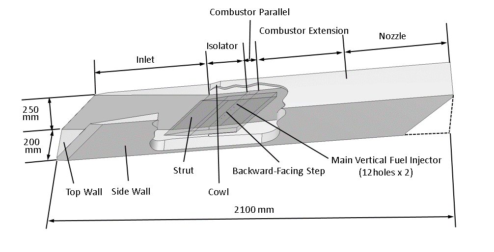
Fig.1: Outline of a scramjet engine tested
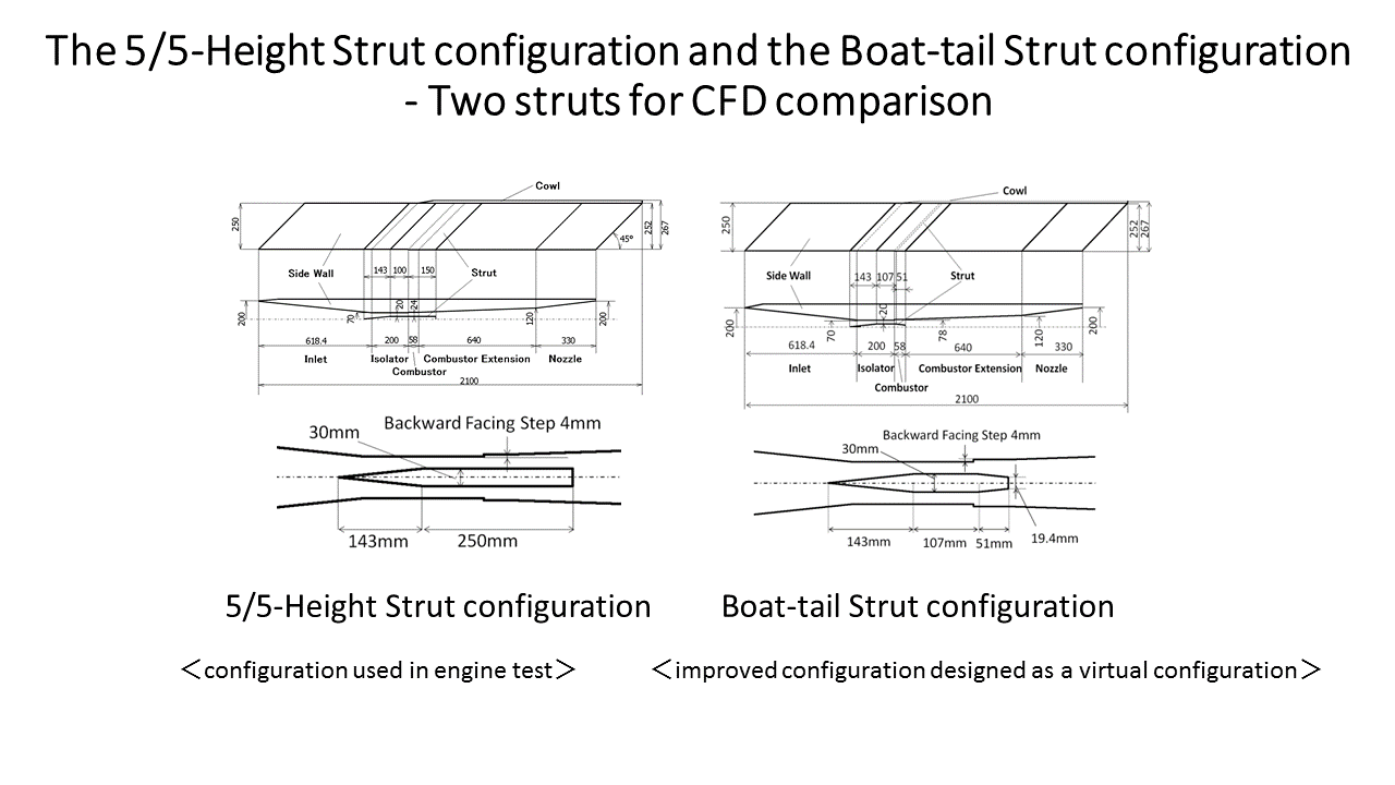
Fig.2: The 5/5-Height Strut configuration and the Boat-tail Strut configuration
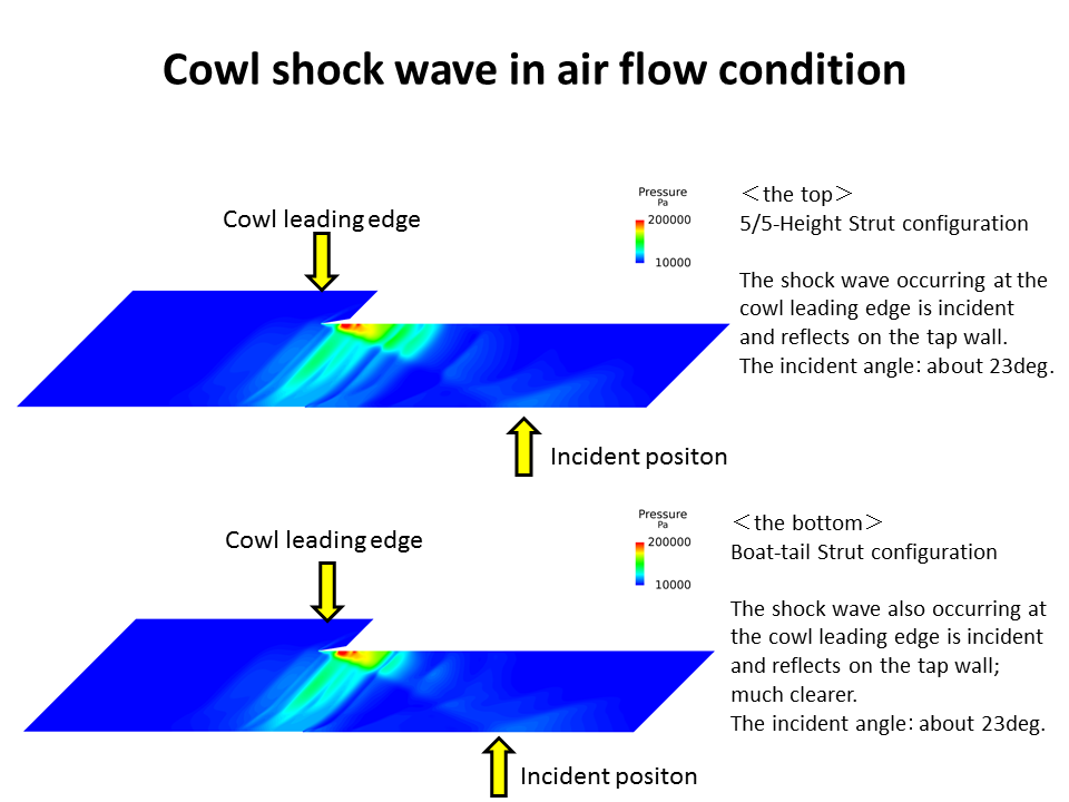
Fig.3: Cowl shock wave in air flow
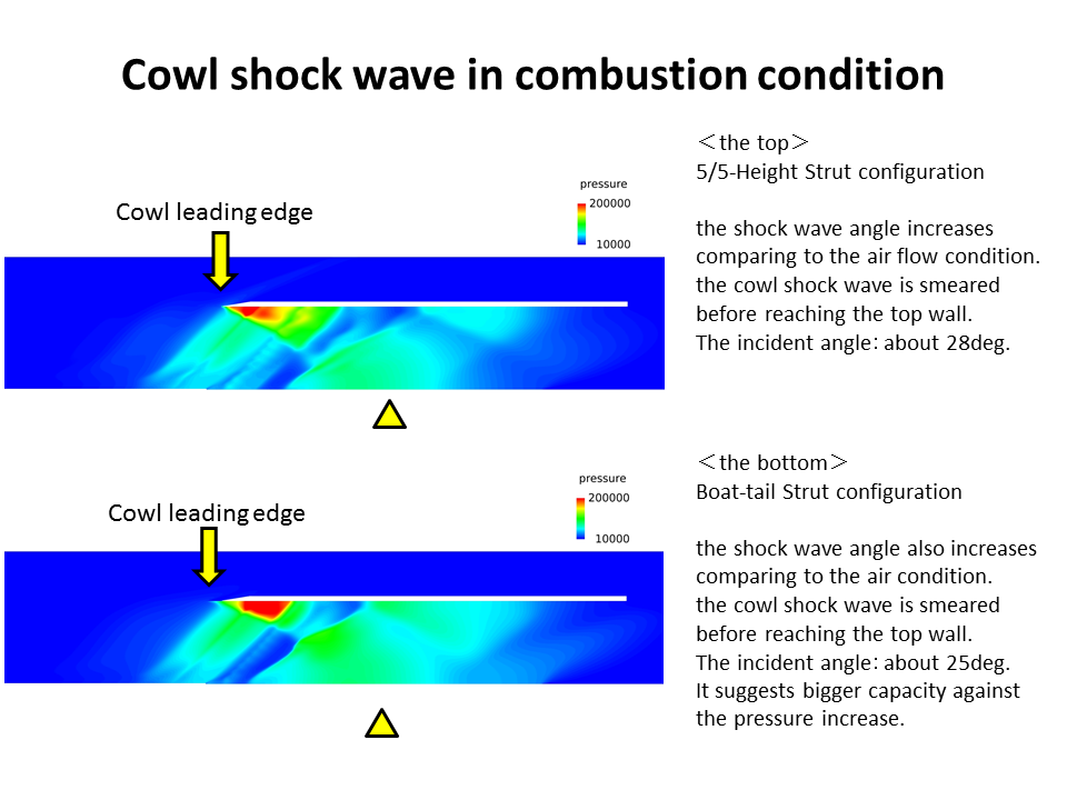
Fig.4: Cowl shock wave in combustion
Publications
■ Presentations
1)Shigeru Sato, Masaaki Fukui, Takahiro Watanabe, Masaharu Takahashiand Toshihiko Munakata,Trial for Improvement in Scramjet Engine Performance, AIAA-2018-0889, Kissimmee, 2018.
Usage of JSS2
Computational Information
- Process Parallelization Methods: It depends on FLUENT
- Thread Parallelization Methods: It depends on FLUENT
- Number of Processes: 2 - 32
- Elapsed Time per Case: 720.00 hours
Resources Used
Fraction of Usage in Total Resources*1(%): 0.03
Details
Please refer to System Configuration of JSS2 for the system configuration and major specifications of JSS2.
| System Name | Amount of Core Time(core x hours) | Fraction of Usage*2(%) |
|---|---|---|
| SORA-MA | 0.00 | 0.00 |
| SORA-PP | 43,179.91 | 0.54 |
| SORA-LM | 48.40 | 0.02 |
| SORA-TPP | 0.00 | 0.00 |
| File System Name | Storage Assigned(GiB) | Fraction of Usage*2(%) |
|---|---|---|
| /home | 039.07 | 0.03 |
| /data | 397.05 | 0.01 |
| /ltmp | 2,115.89 | 0.16 |
| Archiver Name | Storage Used(TiB) | Fraction of Usage*2(%) |
|---|---|---|
| J-SPACE | 0.58 | 0.02 |
*1: Fraction of Usage in Total Resources: Weighted average of three resource types (Computing, File System, and Archiver).
*2: Fraction of Usage:Percentage of usage relative to each resource used in one year.
JAXA Supercomputer System Annual Report April 2017-March 2018