
Turbulence
Analysis of Droplet Group Evaporation
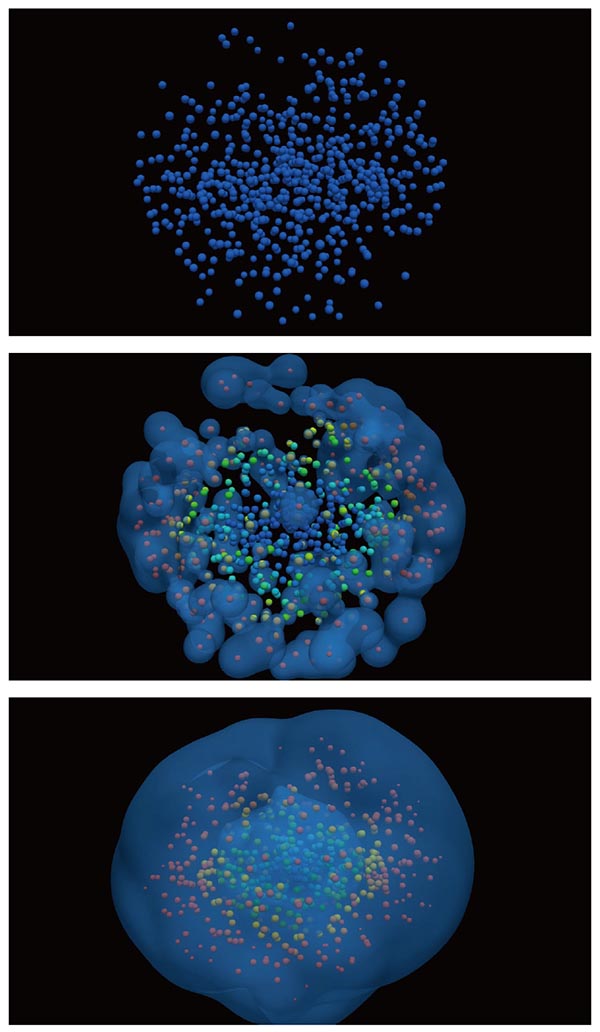
"Group combustion" is an important phenomenon in liquid fuel combustion, in which fuel droplets burn in groups. However, the phenomenon has not been fully understood. In this analysis, we performed the first analysis of group droplet evaporation using the direct numerical simulation which resolves all-region including droplets inside with a computational grid. From this analysis, we can obtain important information such as the change in evaporation rate when droplets form a group, which leads to understanding the group combustion.
Simulation technology to realize front-loading of combustor design process
We try to model complex flow phenomena in a jet engine combustor using detailed numerical simulations. Our current targets are fuel primary atomization and separated turbulent boundary layer.
Limit of gas emissions is being more restrictive, and therefore it is necessary to improve the simulation accuracy. Spatial and size distributions of fuel particle are crucial for the gas emission, and therefore the accurate model is needed for the simulation. However, measurement of fuel primary atomization is difficult, and currently, there is no reliable model. It is one of the bottlenecks of combustor simulations.
We try to model the fuel atomization by a detailed numerical simulation which capture both large liquid core and small particle structures. Although the simulation is challenging because its computational cost is very large due to scale gap of these structures, it has been successfully conducted on about 1 billion computational cells using 2048 CPU cores of JSS2.
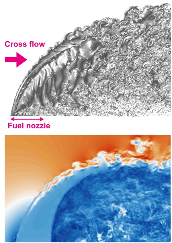
Visualization of liquid phase surface and velocity distribution near the fuel nozzle.
Direct Numerical Simulation of a Turbulent Boundary Layer
with Separation and Reattachment over a wide range of Reynolds numbers
Separation and reattachment of a turbulent boundary layer are crucial issues in aeronautical and engineering applications since they are associated with upper bound of efficiency for the devices. Understanding of the underlying physics and its accurate prediction however may not be still sufficient especially for pressure-induced separated flows. In the present work, we have performed a series of direct numerical simulations (DNSs) for a pressure-induced turbulent separation bubble on a flat plate. A schematic shown here is the current flow configuration. In the present system, suction and blowing are imposed at the upper boundary for producing a separation bubble so that separation and reattached lines (or points) are not fixed in either space or time. The inlet data prescribed are those of a zero-pressure-gradient turbulent boundary layer. The below visualization has been made for the DNS at Reθ=1500 (Reθ denotes the Reynolds number based on the inlet momentum thickness), which is the largest simulation ever performed in this configuration. Number of grid points used are 13 billion to resolve the essential vortical motions.
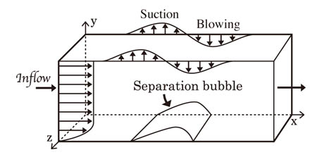
Flow configuration
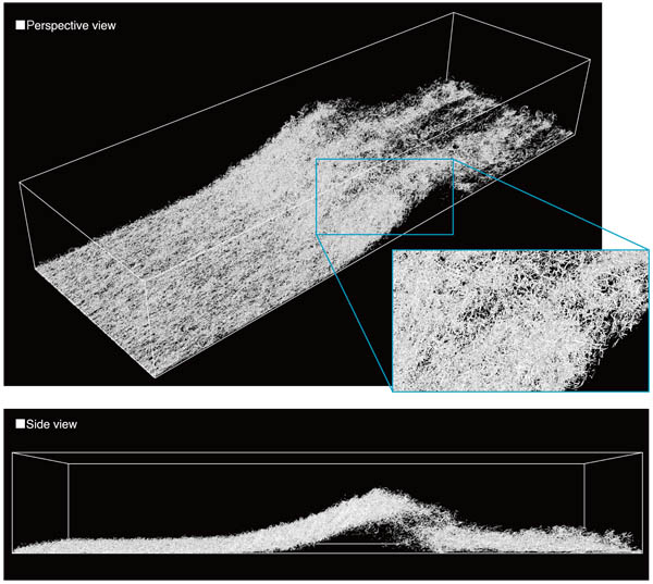
Isosurfaces of Q (the second invariant of fluctuating velocity tensor) : white, positive values.
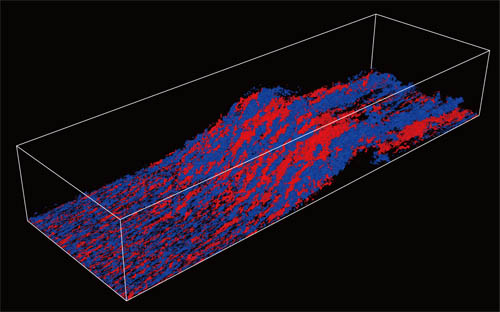
Isosurfaces of u (streamwise velocity fluctuations) : red, positive values; blue, negative values.