
H3 Launch Vehicle
Aeroacoustic Simulation of H3 Launch Vehicle at Lift-off
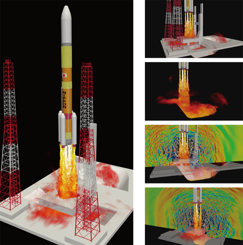
Computational fluid dynamics (CFD) is applied to analyze generation and propagation of acoustic wave generated from Japanese new flagship launch vehicle, H3, at lift-off. Exhaust jets of clustered liquid rocket engines and solid boosters are visualized by volume rendering of the temperature field. Acoustic field is shown by the pressure fluctuation, and it is found that the acoustic wave returns to the launch vehicle.
Large-eddy Simulation of Lift-off Plume Acoustics Using High-order Unstructured Flux-reconstruction Method
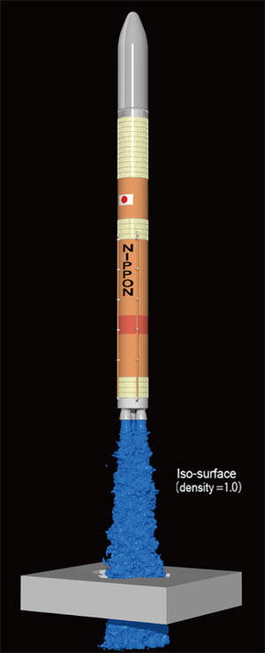
Iso-surface by density
In order to quantitatively predict the acoustic environment at launch vehicle lift-off, it is necessary to accurately simulate the turbulent flow and the acoustic field around the complex geometry of the launch facility. To satisfy the requirement, we have developed a novel high-order unstructured grid solver based on the flux-reconstruction (FR) method, which has flexibility to complex geometries and superior resolution for multi-scale vortices and broad-band sound waves.
Aiming for understanding the effect of different engine configurations on the lift-off acoustics for the H3 launch vehicle, we conducted large-eddy simulation of the exhaust jet from the clustered first-stage engines and its interaction with the launch pad.
The clustered three-nozzles case is presented here. To predict the maximum acoustic load at lift-off, elevation of the launch vehicle was changed by making use of the overset-grid technique without re-meshing the entire computational domain. Since the data transfer between the grids is minimal (only the face values are needed for the FR method instead of multi-layer fringe points), the present approach is suitable for scalable parallel computation.
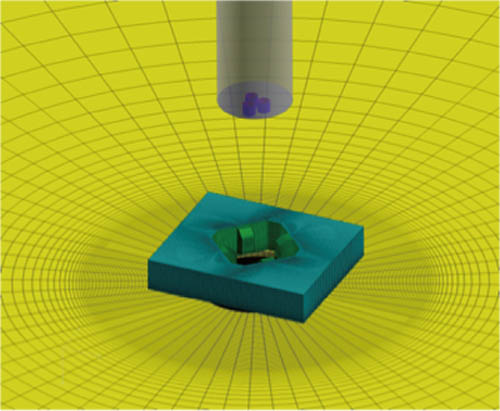
Grid of H3 launch pad
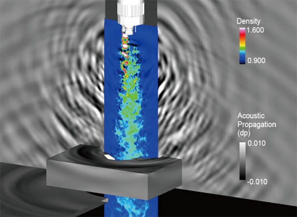
Slice of y =0 density distribution and surface pressure distribution
Movie of the numerical simulation of H3 Launch Vehicle launch pad
Arrangement of Rocket Engines on Jet Flow inside Launch Pad of H3 Launch Vehicle
The research of jet flow of H3 Launch Vehicle inside launch pad
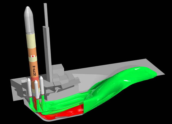
Numerical study is conducted to clarify the effect of rocket engine arrangement on jet flow inside launch pad for Japanese H3 launch vehicle. First stage of the H3 launch vehicle consists in liquid-propellant engines at the center, and solid boosters.
In the configuration having three liquid-propellant engines, it is revealed that the hot jet blows up to the upstream of the flame duct due to the interaction between jet flows. It also turns out that the hot jet blows up if the solid boosters are located lateral direction and interfere the jet from the liquid-propellant engine. The arrangement of the engines should be carefully selected to redirect the hot jets to the downstream of the flame duct safely.
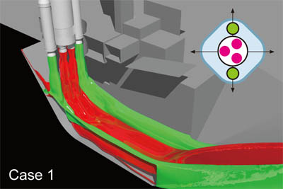
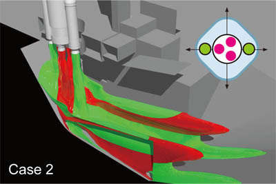
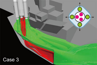
Configuration of Case1, Case2, and Case3 compares the arrangement of two solid boosters. They are located laterally in Case1, while they are set parallel to the flame duct direction. In Cas3, four solid boosters are installed in all the directions.
Jet flow from liquid and solid engines is shown by red-colored, and green-colored iso-surfaces at mass fraction=0.1.
In Case1, the jet flow from the liquid rocket engine interacts with the jet from the solid booster located laterally, and then, pushed back to upstream of the flame duct.
In Case2, the jet flow from the liquid and solid rocket engines goes downstream smoothly. It is found that the solid boosters should be installed so as not to interfere with the jet flow from the liquid engines at the center.
Result of Case3 indicates that jet flow from both of the engines goes downstream without any mutual interference.
More information about H3 Launch Vehicle