Combustion analysis technology
JAXA Supercomputer System Annual Report February 2022-January 2023
Report Number: R22EG3212
Subject Category: Research and Development
- Responsible Representative: Taro Shimizu, Director, Research and Development Directorate, Research Unit III
- Contact Information: Takanori Haga, Research and Development Directorate, Research Unit III(haga.takanori@jaxa.jp)
- Members: Junya Aono, Masaharu Abe, Simon Blanchard, Yu Daimon, Yuma Fukushima, Takanori Haga, Shotaro Hamato, Hiroyuki Ito, Kiyoshi Kumahata, Hirofumi Kurata, Yasuhiro Kawashima, Hideyo Negishi, Takenori Nakajima, Shinji Ohno, Taro Shimizu, Seiji Tsutsumi, Ryoji Takaki, Kazuma Tago
Abstract
In order to capture the unsteady phenomenon in a real-scale liquid rocket engine, the relevant physical models and numerical methods necessary for combustion LES are developed. An analysis tool is validated for the subscale test data, and applied to the development of a real-scale engine.
Reference URL
Please refer to https://stage.tksc.jaxa.jp/jedi/en/simul/index.html .
Reasons and benefits of using JAXA Supercomputer System
Since the flow and combustion in rocket chambers are in a turbulent state and have nonstationary characteristics, LES analysis is essential. Even in this verification target, analysis calculation of about several million steps is required for grid of tens to- hundreds of millions of cells, so it is impossible to achieve the target without using supercomputer.
Achievements of the Year
A combustion solver LS-FLOW-HO based on the Flux Reconstruction (FR) method, which is a high-order accuracy scheme, is under development to realize highly accurate analysis of liquid rocket engine combustors on a real scale. In order to put into practical use a large-scale combustion LES that calculates several hundred injectors, development is proceeding with two pillars: 1) development of a high-speed solver and 2) development of a physical model to reduce the computational cost. So far, we have developed a solver for single-phase flow with supercritical combustion pressure in order to apply it to the analysis of large first-stage engines [1]. In this fiscal year, development of a 3) gas-liquid two-phase solver under subcritical pressure for the evaluation of upper stage engines and throttling performance was also started.
1. Development of high-speed solver (speed-up and validation analysis)
In addition to the LS-FLOW-HO speed-up tuning for the A64FX CPU of the JSS3 TOKI-SORA system, the real fluid models (SRK equation of state and Chung’s transport coefficient model) with large computational cost were speeded up by using regression approximation. It was confirmed that the speedup can be achieved relatively easily by adding coefficients of the regression approximation to the Flamelet table used in the combustion model [2].
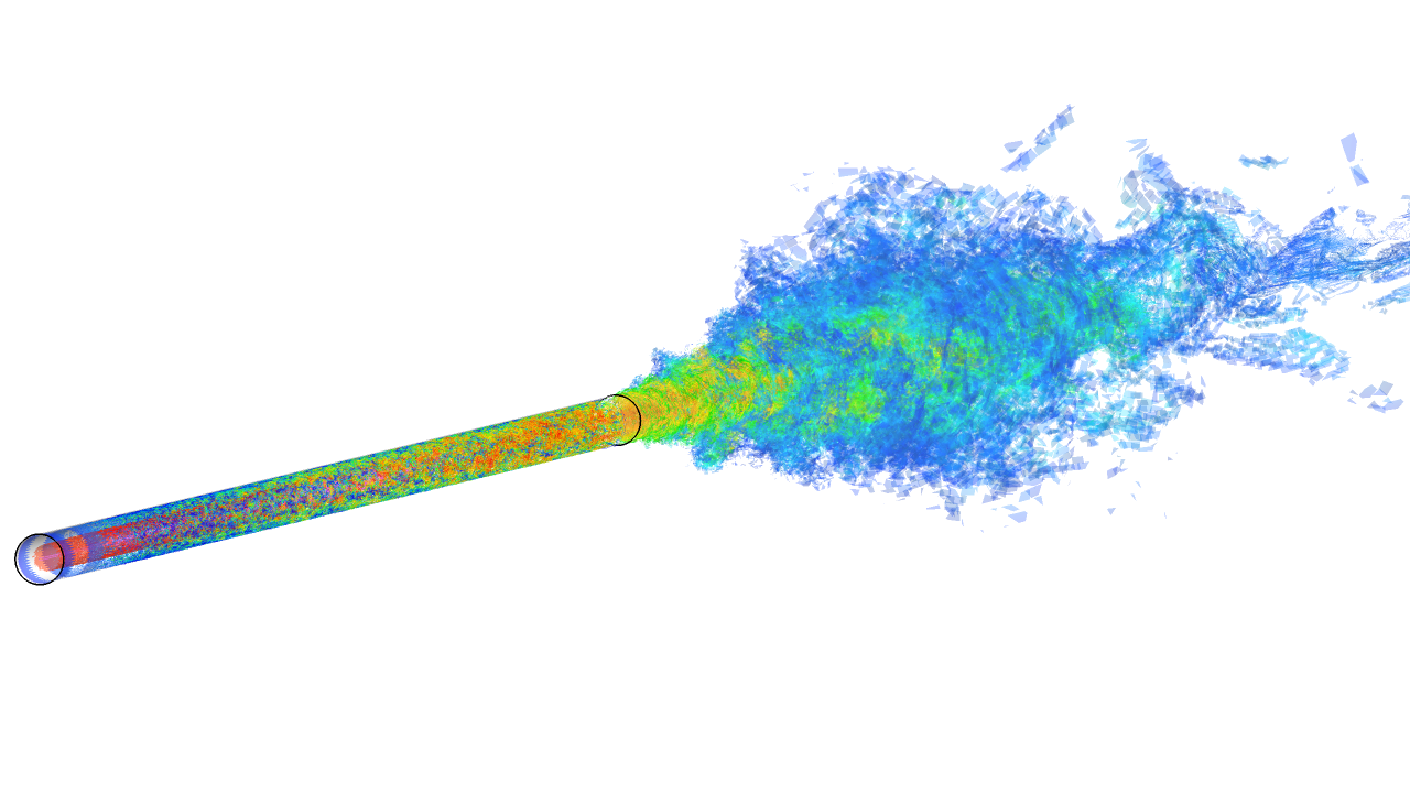
In order to investigate the grid resolution and inflow conditions required for the trans-critical injection of cryogenic propellant, a validation analysis was performed for a cryogenic nitrogen injection experiment. The grid dependence of the turbulent shear layer downstream of the injector outlet was investigated to determine the necessary grid resolution. The potential core of the jet was compared with the experiment, and good agreement was obtained, but the effect of the velocity distribution on the inflow conditions was found to be significant. Currently, we are conducting an analysis that also takes into account the turbulent flow in the circular tube upstream of the injector (Figure 1).
2. Development of physical model (reaction wall model)
To improve the prediction accuracy of the heat flux at the combustor wall, a wall model that takes chemical reactions into account was introduced into LS-FLOW-HO. A wall-modeled LES (WMLES) was conducted for a sub-scale combustor (GOX/GH2) at the Technical University of Munich (Figure 2). Due to the large computational cost of the combustion LES, it was not easy to place more than 25 computational points in each direction for the boundary layer thickness as required by previous studies, and numerical instability occurred when a coarser grid than the criteria was used. The boundary layer develops along the parallel walls of the combustor, and it is assumed that this is due to the fact that the grid resolution is lower where the boundary layer is thin in the middle of its development, resulting in underestimation of turbulent diffusion and a larger error in the temperature gradient in the wall cells. As a remedy, a near wall sub-grid scale model is being tested to compensate for the under-resolved turbulent diffusion based on the assumption of an equilibrium wall model.
3. Development of gas-liquid two-phase solver
Although there are many models for gas-liquid two-phase flow, the diffused interface model was adopted because it can be extended based on the single-phase flow solver that has been developed so far and because it is superior in large-scale parallelism. A four-equation model that assumes mechanical and thermal equilibrium was adopted and implemented in LS-FLOW-HO. The equation of state for the liquid phase is based on NASG. The Chiapolino’s model is adopted as the phase change model and extended to consider multi-component chemical species. Experiments with coaxial jets of liquid and gaseous nitrogen were used for verification, and the results of the two-dimensional calculations are shown in Figure 3. To improve the reproducibility of liquid nitrogen atomization in the shear layer, we are currently experimenting with the introduction of a surface tension model.

Fig.1: LES with a circular jet of cryogenic nitrogen; chamber pressure is 3.97 MPa, nitrogen injection temperature is 126.9 K, and injection velocity is 4.9 m/s.

Fig.2: Instantaneous temperature field of a TUM single-element combustor (GOX/GH2) with wall model LES.

Fig.3: 2D simulation of a non-reactive coaxial jet consisting of a central jet that is liquid cryogenic nitrogen (subcritical conditions, due to the ambient pressure of 15 bar) surrounded by gaseous nitrogen. The evaporation process is included.
Publications
– Non peer-reviewed papers
[1] Haga, T., Fukushima, Y., Kumahata, K., Negishi, H., Shimizu, T., “For Large-Eddy Simulations of a Liquid Rocket Engine Full-Scale Combustor,” Journal of the Combustion Society of Japan, Vol.64(208), 126-135, 2022. (In Japanese)
[2] Haga, T., Aono, J., Fukushima, Y., Shimizu, T., “On speed-up of supercritical pressure turbulent diffusion flame simulation based on flamelet model,” 60th Combustion symposium (Japan), K114, 2022. (In Japanese)
– Invited Presentations
Haga, T., Fukushima, Y., Kumahata, K., Shimizu, T., “Large-Eddy Simulations of Supercritical Jet Flames by Flux-Reconstruction Method with Invariant-Region-Preserving Limiter,” 15th World Congress on Computational Mechanics & 8th Asian Pacific Congress on Computational Mechanics, 2022.
Usage of JSS
Computational Information
- Process Parallelization Methods: MPI
- Thread Parallelization Methods: OpenMP
- Number of Processes: N/A – 2000
- Elapsed Time per Case: 336 Hour(s)
JSS3 Resources Used
Fraction of Usage in Total Resources*1(%): 3.59
Details
Please refer to System Configuration of JSS3 for the system configuration and major specifications of JSS3.
| System Name | CPU Resources Used(Core x Hours) | Fraction of Usage*2(%) |
|---|---|---|
| TOKI-SORA | 91522322.93 | 3.99 |
| TOKI-ST | 318898.09 | 0.32 |
| TOKI-GP | 201951.29 | 8.59 |
| TOKI-XM | 0.00 | 0.00 |
| TOKI-LM | 766.27 | 0.05 |
| TOKI-TST | 177895.67 | 4.69 |
| TOKI-TGP | 0.00 | 0.00 |
| TOKI-TLM | 0.00 | 0.00 |
| File System Name | Storage Assigned(GiB) | Fraction of Usage*2(%) |
|---|---|---|
| /home | 2515.32 | 2.28 |
| /data and /data2 | 143670.80 | 1.11 |
| /ssd | 1902.07 | 0.26 |
| Archiver Name | Storage Used(TiB) | Fraction of Usage*2(%) |
|---|---|---|
| J-SPACE | 173.94 | 0.77 |
*1: Fraction of Usage in Total Resources: Weighted average of three resource types (Computing, File System, and Archiver).
*2: Fraction of Usage:Percentage of usage relative to each resource used in one year.
ISV Software Licenses Used
| ISV Software Licenses Used(Hours) | Fraction of Usage*2(%) | |
|---|---|---|
| ISV Software Licenses(Total) | 13153.69 | 9.15 |
*2: Fraction of Usage:Percentage of usage relative to each resource used in one year.
JAXA Supercomputer System Annual Report February 2022-January 2023


