
Wall-modeled large-eddy simulation for prediction of wall heat flux in rocket engine combustor
JAXA Supercomputer System Annual Report February 2022-January 2023
Report Number: R22EFHC0305
Subject Category: Large-Scale Challenge
- Responsible Representative: Naoyuki Fujita, Manager, Security and Information Systems Department, Supercomputer Division
- Contact Information: Takanori Haga, Research and Development Directorate, Research Unit III(haga.takanori@jaxa.jp)
- Members: Yuma Fukushima, Takanori Haga, Hiroyuki Ito
Abstract
A large-eddy simulation (LES) is performed to quantitatively evaluate the wall heat flux in a sub-scale rocket engine combustor.
Accurate prediction of wall heat flux is necessary to assess the risk of melt damage to the combustor wall and the heat-absorption performance of regenerative-cooling engines. JAXA has previously proposed a wall model for reactive turbulent boundary layers, and we will verify its effectiveness in reducing computational cost and improving prediction accuracy by applying it to the LES of a combustor. Specifically, wall heat flux and combustion pressure will be evaluated and compared with experimental data and conventional RANS results. The grid resolution required for wall-modeled LES (WMLES) is also investigated.
Although this study focuses on rocket engines, the proposed method is applicable to the simulation of other combustors and wall turbulence with reactions. The results of this project will be published in international conferences and journals.
Reference URL
N/A
Reasons and benefits of using JAXA Supercomputer System
There are few examples of rocket engine sub-scale combustor analyses using WMLES to model wall stresses and heat fluxes, and no previous studies have investigated grid convergence, which rapidly increases the computational cost. In this project, a computational grid of 400 million points is used, about 4 times larger than in the previous computation. An explicit scheme was used for the time integration due to its excellent parallelism. So, the time step limited by the minimum grid size near the wall is small, and at least several million steps are required to evaluate turbulence statistics. The combination of LS-FLOW-HO, a high-speed solver for large-eddy simulation developed by JAXA, and the computing power of JAXA’s JSS3 supercomputer will enable this computation with a sufficient physical time length.
Achievements of the Year
1. Case description
The object of the simulations is a single-element rocket engine combustor that was tested at the Technical University of Munich (TUM), in which the gases oxygen and hydrogen are injected from a coaxial injector. The combustion chamber is 12 mm in diameter and approximately 300 mm long, and the fuel and oxidizer flow downstream to the nozzle while mixing and burning. The fuel and oxidizer are accelerated to supersonic speeds at the nozzle throat and flow out of the downstream boundary. The mixing ratio is set to 5.24, and the temperature of the cooled combustor wall is given by linear interpolation of the experimentally obtained distribution.
2. Computational methods
A high-order unstructured grid method, the flux reconstruction (FR) method, is used for discretization, and a table-referenced non-adiabatic flamelet progress variable model that takes heat loss into account is used for the combustion model. A four-stage third-order accurate Strong-Stability preserving Runge-Kutta explicit method is used for time integration. The chemical composition of the thermally turbulent boundary layer near the cooling wall is evaluated using a wall model that assumes a chemical equilibrium suitable for hydrogen, which has a high reaction rate. The wall model requires a specified distance from the wall (matching height) to provide the LES solution of the outer boundary layer as input, which is 10% of the thermal boundary layer thickness (evaluated from RANS results) 75 mm downstream from the injection surface. In the preliminary computation, numerical instability was observed in the case of coarse grid resolution due to unphysical degradation of the temperature distribution near the wall, which may be caused by insufficient resolution of the thin developing boundary layer in the WMLES grid. This is thought to be due to a lack of turbulent mixing and errors caused by approximating the temperature gradient near the wall with high-order polynomials. To solve the issue, the wall model was augmented by adding SGS viscosity (mixing length model) in the LES grid below the matching height. The inflow boundary was given an exponential velocity distribution with a correction based on the Reynolds number, and the outflow boundary was assumed to be a supersonic outflow. The injector interior and faceplate were given adiabatic, no-slip boundaries, and the combustor wall and nozzle were given isothermal, no-slip boundaries. The calculations were performed for approximately 7 ms, and the latter 5 ms were time-averaged. Averaging was also performed in the circumferential direction.
3. calculation results
Figure 1 compares the results of the preliminary computation on the coarse grid (100 million points) with the results of this project on the fine grid (400 million points). The grid resolution of the coarse grid is 10, 72, and 20 points in the flow, wall normal, and circumferential directions, respectively. The grid resolution used in this project is almost twice that of the coarse grid in the axial and circumferential directions, and thus almost meets the criteria. In the figure, the effect of the resolution improvement can be seen in finer structures appearing on the flame surface represented by the stoichiometric mixing fraction Z=Zst.
A comparison of the heat flux on the combustor wall predicted by WMLES with experimental and RANS results is shown in Figure 2. The results for the coarse grid (100 million points) and the grid with twice as many points in the flow direction (200 million points) are similar to the RANS results up to 0.15 m from the injection surface, but after 0.2 m, the WMLES results are lower and closer to the experimental values. Unlike these results, the WMLES result of the twice circumferential resolution (400 million points) overestimated the heat flux. In the case of insufficient grid resolution, eddy viscosity was introduced as an SGS model to compensate for the under-resolved Reynolds stress, but this may be due to the fact that a constant viscosity is given regardless of the grid resolution. The coarse grid cases added eddy viscosity to the flow field that was not resolved by the grid, and this may have resulted in improved diffusion and stabilization of the calculation. On the other hand, with sufficient grid resolution, an excess diffusion was added to the flow field, resulting in a hotter region closer to the wall (Figure 3). Thus, the wall model overestimated the wall heat flux using this higher temperature as input. The combustion pressure was slightly lower than the experimental and RANS values, which was independent of the grid resolution.
Although the grid convergence of heat flux was not achieved in this project, the investigation of the grid dependence by large-scale analysis allowed us to identify the source of the WMLES error in the flow field of a sub-scale combustor. It was also found that circumferential grid resolution was more important than axial grid resolution for the grid dependence of the flow field. Since the analysis of a full-scale combustor involves tens of billions of points with hundreds or more injectors, it is not easy to meet the recommended grid resolution of WMLES, and it is essential to improve the model to have less grid dependence even on a coarse grid for practical analysis. Detailed analysis of the turbulence statistics obtained in this project is providing guidelines for improving the near-wall SGS model, which will be validated and applied to real engine problems in the future.

Fig.1: Comparison of previous result of coarse grid (0.1 billion DoFs, upper) and current result of refined grid (0.4 billion DoFs, lower). Iso-surface distribution of stoichiometric mixture fraction Z=Zst and temperature distribution of the cross-sectional surface (300 K (blue)≦T≦3500 K (pink)) are shown.
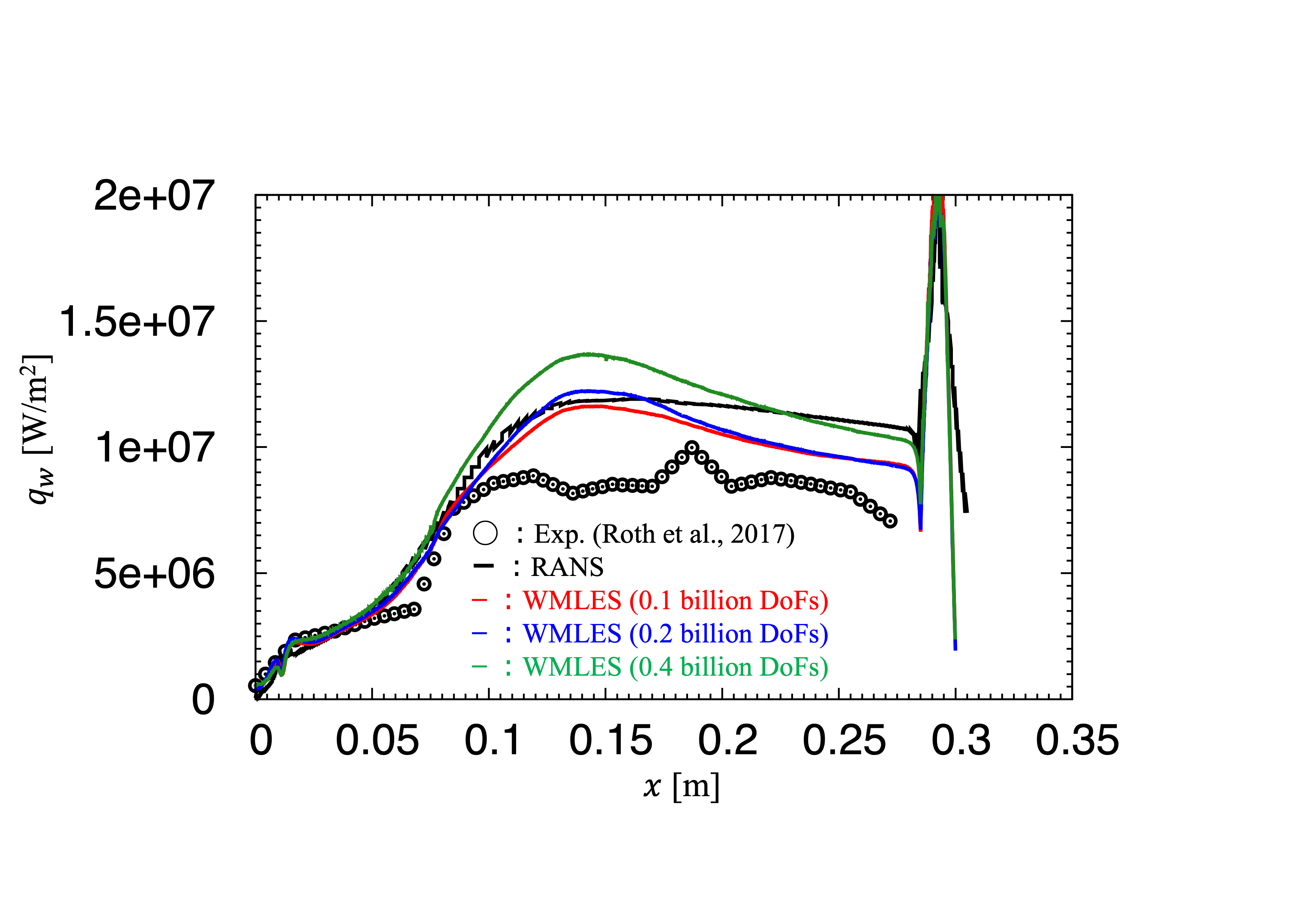
Fig.2: Circumferentially-averaged heat flux distribution on the combustor wall from the faceplate position (?=0 m) to the nozzle outlet (?=0.3 m).
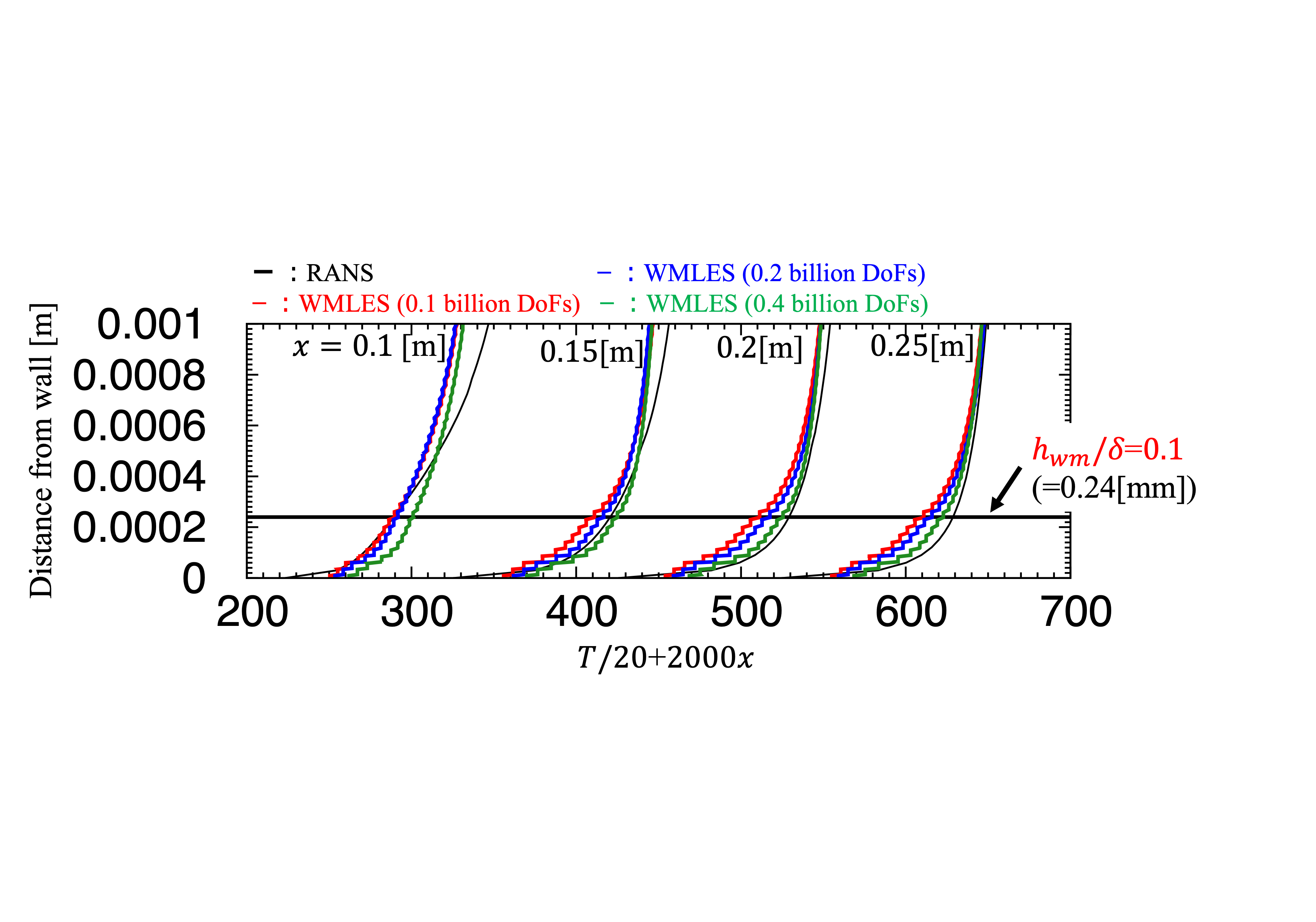
Fig.3: Circumferentially-averaged temperature distribution near the combustor wall at each axial position from the faceplate position (?=0 m).
Publications
N/A
Usage of JSS
Computational Information
- Process Parallelization Methods: MPI
- Thread Parallelization Methods: OpenMP
- Number of Processes: 2000
- Elapsed Time per Case: 482.4 Hour(s)
JSS3 Resources Used
Fraction of Usage in Total Resources*1(%): 1.54
Details
Please refer to System Configuration of JSS3 for the system configuration and major specifications of JSS3.
| System Name | CPU Resources Used(Core x Hours) | Fraction of Usage*2(%) |
|---|---|---|
| TOKI-SORA | 42012766.00 | 1.83 |
| TOKI-ST | 0.00 | 0.00 |
| TOKI-GP | 0.00 | 0.00 |
| TOKI-XM | 0.00 | 0.00 |
| TOKI-LM | 0.00 | 0.00 |
| TOKI-TST | 0.00 | 0.00 |
| TOKI-TGP | 0.00 | 0.00 |
| TOKI-TLM | 0.00 | 0.00 |
| File System Name | Storage Assigned(GiB) | Fraction of Usage*2(%) |
|---|---|---|
| /home | 158.82 | 0.14 |
| /data and /data2 | 17364.71 | 0.13 |
| /ssd | 1331.06 | 0.18 |
| Archiver Name | Storage Used(TiB) | Fraction of Usage*2(%) |
|---|---|---|
| J-SPACE | 32.54 | 0.14 |
*1: Fraction of Usage in Total Resources: Weighted average of three resource types (Computing, File System, and Archiver).
*2: Fraction of Usage:Percentage of usage relative to each resource used in one year.
ISV Software Licenses Used
| ISV Software Licenses Used(Hours) | Fraction of Usage*2(%) | |
|---|---|---|
| ISV Software Licenses(Total) | 0.00 | 0.00 |
*2: Fraction of Usage:Percentage of usage relative to each resource used in one year.
JAXA Supercomputer System Annual Report February 2022-January 2023