
Air flow distribution control by a fluidic element
JAXA Supercomputer System Annual Report April 2016-March 2017
Report Number: R16E0109
- Responsible Representative: Hisao Futamura(Aeronautical Technology Directorate, Propulsion Research Unit)
- Contact Information: Seiji Yoshida(yoshida.seiji@jaxa.jp)
- Members: Seiji Yoshida, Mitsumasa Makida, Naoki Nakamura, Takeishi Ikumi
- Subject Category: Aviation(Aircraft engine)
Abstract
Lean combustion is promising to reduce nitrogen oxide emission from jet-engines. To solve combustion instability, that is a problem of lean combustion, a pilot burner for ensuring stable combustion and a main burner for performing lean, low-NOx combustion are used. The purpose of this study is improvement of combustor performance by controlling air flow rate distribution between the pilot burner and the main burner using a fluidic element, which has no moving part.
Goal
By controlling an air-flow in a jet engine combustor, improve a jet engine combustor performance such as improvement of combustion efficiency,suppression of combustion instability.
Objective
Investigation of air flow rate distribution characteristic of fluidic elements depending on output channel resistances and its geometries.
References and Links
Please refer 'Advanced combustion technologies for small, high-output core engines | Propulsion technology | Aeronautical Technology Directorate'.
Use of the Supercomputer
Parametric study of influence of geometry of fluidic elements on air flow rate distribution. And visualization of internal flow of fluidic element to get knowledge for improvement of fluidic-element geometry.
Necessity of the Supercomputer
It is necessary that numerous CFD analysis about geometry of fluidic elements to optimize its geometry.
Achievements of the Year
In order to match the numerical analysis conditions and the experiment conditions, numerical analysis were conducted for more than 20 computational grids of the fluidic element with different exit area. As a result, it was confirmed that the experiment result and the CFD result agree. Numerical analysis was also conducted for about 20 patterns with different geometry of flow path, and we obtained some findings like separation point of the flow inside the fluidic element.
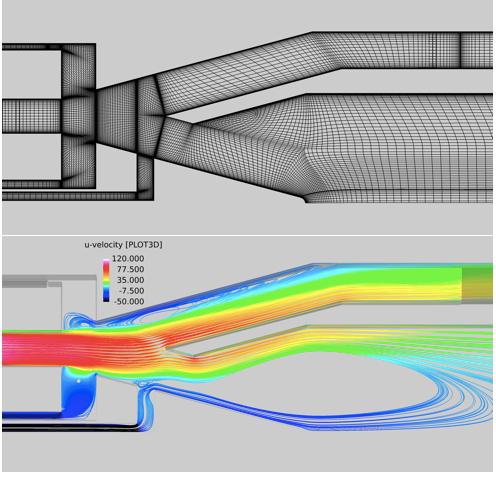
Fig.1:Computational grid and flow field of the fluidic element
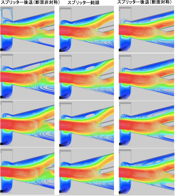
Fig.2:Comparison of separation point in each fluidic elements with different geometry
Publications
N/A
Computational Information
- Parallelization Methods: Hybrid Parallelization
- Process Parallelization Methods: MPI
- Thread Parallelization Methods: Automatic Parallelization
- Number of Processes: 36
- Number of Threads per Process: 16
- Number of Nodes Used: 18
- Elapsed Time per Case (Hours): 50
- Number of Cases: 40
Resources Used
Total Amount of Virtual Cost(Yen): 1,762,505
Breakdown List by Resources
| System Name | Amount of Core Time(core x hours) | Virtual Cost(Yen) |
|---|---|---|
| SORA-MA | 1,041,492.92 | 1,700,258 |
| SORA-PP | 1,134.64 | 9,687 |
| SORA-LM | 0.00 | 0 |
| SORA-TPP | 0.00 | 0 |
| File System Name | Storage assigned(GiB) | Virtual Cost(Yen) |
|---|---|---|
| /home | 29.54 | 278 |
| /data | 2,008.08 | 18,942 |
| /ltmp | 3,534.23 | 33,338 |
| Archiving System Name | Storage used(TiB) | Virtual Cost(Yen) |
|---|---|---|
| J-SPACE | 0.00 | 0 |
Note: Virtual Cost=amount of cost, using the unit price list of JAXA Facility Utilization program(2016)
JAXA Supercomputer System Annual Report April 2016-March 2017