
Ground test validation of high-speed airbreathing engine design method with wide operation range
JAXA Supercomputer System Annual Report February 2024-January 2025
Report Number: R24ECMP35
Subject Category: Competitive Funding
- Responsible Representative: Hideaki Nanri, Director, Research Unit IV, Research and Development Directorate
- Contact Information: Masahiro Takahashi(takahashi.masahiro@jaxa.jp)
- Members: Masaaki Fukui, Susumu Hasegawa, Taku Inoue, Masatoshi Kodera, Toshihiko Munakata, Sadatake Tomioka, Masahiro Takahashi
Abstract
Hypersonic air-breathing engines can be efficient for winged launch vehicles and high-speed vehicles for peer-to-peer transportation. For example, a high-speed vehicle with a Mach number above 5.5 in flight is reported to have a good potential market. However, no single airbreathing engine can operate over a wide range of speeds from takeoff to Mach 5.5 and above, so combined cycle engines are required for such applications. Various types of combined cycle engines have been proposed, and currently, turbine-based combined cycle engines are under development or in the technical demonstration phase, mainly for Mach 5 vehicles. A combination with scramjet is necessary for higher velocity, say Mach 6, bringing a further challenge to engine design technology, which is not mature yet. Therefore, JAXA is collaborating with several universities on a five-year research program to develop key technologies needed for the development of a TBCC engine, which is a combination of a turbo-ramjet and a scramjet with a flow-pass switching mechanism, and to demonstrate them through ground tests.
Reference URL
N/A
Reasons and benefits of using JAXA Supercomputer System
Taking scramjet research as an example, one of the main tasks of this research is to design the geometry of the air inlet, combustor flow path, fuel injector, and cavity flame holder. These are then manufactured and tested on the ground to confirm their performance. To keep the candidate geometry selection process on schedule, many parametric computations must be performed within a limited time frame. In particular, the computational cost of CFD of scramjet combustors increases significantly because the combustion process of hydrocarbon fuels involves many intermediate species, and the combustion reaction models are complex and extensive. Therefore, using JSS, which has high computational power, is essential.
Achievements of the Year
(1) Investigation of a scramjet inlet with a wide operating range
To extend the low-speed operating range of the scramjet, one of the technical issues to be addressed in the development of the TBCC engine that combines a turbo-ramjet and a scramjet, the shape of a scramjet inlet that operates over a wide range of Mach numbers was investigated using CFD. A two-dimensional multi-stage ramp-compression type air inlet was designed to achieve 100% air capture efficiency under cruise conditions (flight Mach number 6, and dynamic pressure 50 kPa), and its startability and performance under off-design conditions (flight Mach number 5, 4, 3.5, and dynamic pressure 50 kPa) were evaluated using 2D RANS. Eventually, it will be necessary to introduce moving parts to ensure stable operation at low speeds, but if the introduction of moving parts is kept to a minimum, the drive system and auxiliary equipment can be made smaller, which is expected to improve the ease of the implementation and suppress weight gain. For this reason, the goal was to maximize the operating range of the base fixed flow-path geometry. Figure 1 shows the Mach number contours for an inlet with three external and two internal compression ramps. The figures on the left show the results of an inlet designed with a pressure ratio of 50 between the entrance and exit pressures, and those on the right show the results of an inlet designed with a pressure ratio of 40. When the pressure ratio was 50, the inlet started down to the Mach 4 condition, but at the Mach 3.5 condition, it became unstart condition, unable to draw in a supersonic flow. On the other hand, when the pressure ratio was reduced to 40, the inlet was maintained in the start state at the Mach 3.5 condition. This is because the minimum cross-sectional area of the internal flow-path increased, allowing more air to be drawn in.
(2) Improved design of supersonic combustor, fuel injector, and cavity flame-holder
In order to evaluate the feasibility and effectiveness of the improved fuel injector as soon as possible, the candidates of fuel injectors that can be installed in the existing combustor test model were selected based on combustion CFD evaluation, and the selected injector test models were manufactured. The combustion tests are scheduled to be conducted in the next fiscal year. In order to expand the operating range and achieve the required thrust level for the assumed flight mission, we have started to consider improvements to the entire supersonic combustor, including the combustor flow-path shape and the cavity flame-holder, in addition to the fuel injector and have conducted combustion CFD evaluations of several candidate geometries.
(3) Heat flux prediction for ramjet air duct internal wall
To evaluate the feasibility of cooling the airflow duct for the ramjet, which is installed around the core turbojet of the turbo-ramjet, by fuel, the heat flux received by the inner surface of the duct was estimated using CFD.
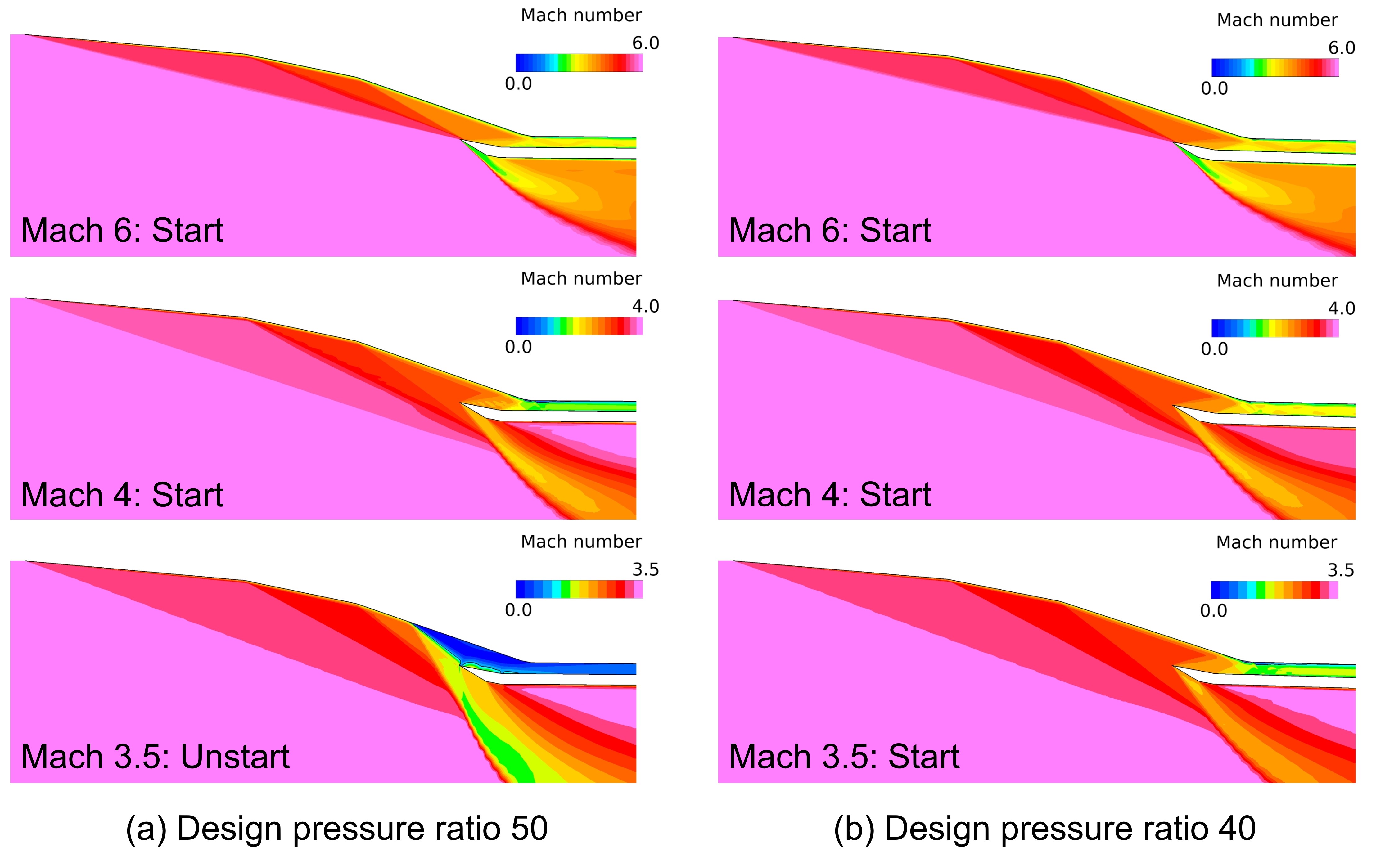
Fig.1: Mach number contours of 2D scramjet inlet with three external and two internal compression ramps.
Publications
- Non peer-reviewed papers
Masahiro Takahashi, et al., ''Design of a Scramjet Inlet with a Wide Operating Range,'' Proceedings of the 68th Ukaren, 1J02, 2024 (in Japanese).
- Oral Presentations
Masahiro Takahashi, et al., ''Design of a Scramjet Inlet with a Wide Operating Range,'' The 68th Ukaren, 1J02, 2024.
Usage of JSS
Computational Information
- Process Parallelization Methods: MPI
- Thread Parallelization Methods: N/A
- Number of Processes: 48 - 4800
- Elapsed Time per Case: 40 Hour(s)
JSS3 Resources Used
Fraction of Usage in Total Resources*1(%): 0.84
Details
Please refer to System Configuration of JSS3 for the system configuration and major specifications of JSS3.
| System Name | CPU Resources Used(Core x Hours) | Fraction of Usage*2(%) |
|---|---|---|
| TOKI-SORA | 22681632.01 | 1.04 |
| TOKI-ST | 13448.15 | 0.01 |
| TOKI-GP | 0.00 | 0.00 |
| TOKI-XM | 0.00 | 0.00 |
| TOKI-LM | 0.00 | 0.00 |
| TOKI-TST | 0.76 | 0.00 |
| TOKI-TGP | 0.00 | 0.00 |
| TOKI-TLM | 0.00 | 0.00 |
| File System Name | Storage Assigned(GiB) | Fraction of Usage*2(%) |
|---|---|---|
| /home | 171.05 | 0.12 |
| /data and /data2 | 13485.79 | 0.06 |
| /ssd | 102.67 | 0.01 |
| Archiver Name | Storage Used(TiB) | Fraction of Usage*2(%) |
|---|---|---|
| J-SPACE | 8.46 | 0.03 |
*1: Fraction of Usage in Total Resources: Weighted average of three resource types (Computing, File System, and Archiver).
*2: Fraction of Usage:Percentage of usage relative to each resource used in one year.
ISV Software Licenses Used
| ISV Software Licenses Used(Hours) | Fraction of Usage*2(%) | |
|---|---|---|
| ISV Software Licenses(Total) | 2763.93 | 1.89 |
*2: Fraction of Usage:Percentage of usage relative to each resource used in one year.
JAXA Supercomputer System Annual Report February 2024-January 2025