
Research for Future Transportation System (Research for Scramjet Engine Flow Path)
JAXA Supercomputer System Annual Report April 2020-March 2021
Report Number: R20EG3104
Subject Category: Research and Development
- Responsible Representative: Shigeru Sato, Researcher, Research Unit 4, Research and Development Directorate
- Contact Information: Shigeru Sato, Researcher, Research Unit 4, Research and Development Directorate, sato.shigeru@jaxa.jp(sato.shigeru@jaxa.jp)
- Members: Shigeru Sato, Toshihiko Munakata, Masaaki Fukui, Masaharu Takahashi, Taku Inoue
Abstract
The purpose is to investigate the influence of the internal flow path on the engine performance by help of CFD in the viewpoint of aerodynamics about a scramjet engine as a reusable space propulsion engine, and to contribute to designing a scramjet engine.
In other words it is to compare the engine results with CFD in order to extract effective factors on improvement of the engine performance from a lot of experimental results of engine tests stored in Kakuda Space Center, and to make CFD simulation about a trial engine configuration which is proposed for engine performance improvement.
Reference URL
Please refer to '宇宙航空研究開発機構リポジトリ(予定)'.
Reasons and benefits of using JAXA Supercomputer System
In Kakuda Space Center, scramjet engine is being investigated, and a lot of engine performance tests have been made by using Ramjet Engine Test Facility (RJTF). It has been found in the tests that the difference of engine inner configuration produces large difference of thrust performance in the flight condition of Mach 6. CFD simulations are being carried out based on the plenty of engine test data stored in Kakuda Space Center about how the difference of engine inner configuration of main elements of the engine, inlet, isolator, strut and others influent on the engine performance, and CFD simulations on trial engine configuration not yet tested are also carried out.
Achievements of the Year
In order to compare to the result of engine configuration already tested in RJTF (Ramjet Engine Test Facility) located in Kakuda Space Center, a virtual engine test is being carried out about an improved engine configuration. The configuration has a boat-tail strut of which the tail is shortened and narrowed in order to improve the engine thrust performance, though it has the same basic dimension to the tested engine. Figure 1 shows the tested engine outline and the both configurations. Figure 2 shows the difference of engine inner quantity in the both engine configurations.
A commercial code ANSYS Fluent is applied to this calculation, and structured grid system is used. The minimum grid size is set by 0.1mm near the cowl leading edge. The calculation is done in the half of the engine model assuming mirror condition in the engine symmetric center plane. The number of grids at the maximum is 5.03x10⁶. The limiter is the second order accuracy, space integral is AUSM+, time integral is explicit method, and turbulence model is k-omega model. For the combustion calculation, a model used here is the model of Fluent including Hydrogen-Oxygen reaction equation based on the Petersen and Hanson (1999). This time Finite Rate Chemistry Model is employed for the combustion calculation, and the reaction consists of 9 species and 20 elementary reactions.
Engine air flow condition for calculation is set at Mach 5.3 in the engine entrance, and total temperature is set at 1500K. RJTF nozzle exit boundary layer (57.9mm thickness / 99.9% of main stream velocity) is also set in the flows into the engine, which corresponds to the boundary layer on the air frame bottom surface.
Figure 3 shown below gives the position and size of the separation on the horizontal cut by 1mm up from the top wall in the half of the engine from the center line, and the color indicates the temperature. What the authors call separation is the region where the velocity is less than -0.01m/s. According to Fig.3, the separation position and the temperature rise can be seen, and how the fuel mixing effect caused by the separation can influence the combustion, as well.
Figure 3a gives the case of 5/5-Height Sturt configuration, and Fig.3b gives the case of Boat-tail Strut configuration. In this scope are included the rest of inlet, the backward-facing step, the combustor parallel, the combustor expansion and the nozzle. The flow runs from the left to the right.
In Fig.3a are found the separation point at 1044mm downstream from the inlet leading edge and the reattachment point at 1253mm also. The separation region is enclosed with white line. At the same time seeing the temperature, the temperature increases at the separation point, and the high temperature is distributed toward the downstream continuously.
What occurs in Fig.3 suggests that the fuel mixing is promoted from the separation point to drive the reaction and to release more heat in the recirculating region.
Also the result of Boat-tail Strut configuration is presented in Fig.3b. This strut shortens and narrows at the tail, and the shape is confirmed in Fig.3b. The separation point is at 933mm downstream from the inlet leading edge, and the reattachment point is 1210mm also, so that the separation point is found to move upstream to enlarge the separation region. In this configuration the temperature increases at the separation point as well. Additionally, the high temperature region expands wider than in the case of 5/5-Height Strut configuration described above.
Being based on the two results shown above, it is recognized that the separation promotes the fuel mixing which drives the reaction to bring the temperature increase.
It can be said that treating the separation region has the importance to confirm the engine performance in the calculation. If the separation region stays in an appropriate size, it can be thrust source, but if too much, it can cause the separation all over the top wall to bring the engine unstart and thrust loss. It is necessary to consider and design a method of controlling the separation in the engine internal flow.
The separation is overestimated in this calculation, but the combustion is otherwise, rather underestimated. The thrust calculated by pressure distribution integral is less than the measured thrust. Though it is needed to find out the cause why the combustion is underestimated, the mixing is not able to be simulated enough in the calculation. Mixing accuracy of models needs to be chosen and to be evaluated.
Figure 4 shown below gives the pressure distribution on the top wall in each configuration. They are the pressure distributions on the horizontal cut by 1mm up from the top wall. Figure 4a shows the 5/5-Height strut configuration, and Figure 4b gives the Boat-tail strut configuration, where the scope includes the rear part of strut, the backward-facing step on the side wall, the combustion parallel and the combustion expansion. In the both configurations, an expansion wave occurs at the strut tail and goes into some part of side wall, namely the combustion expansion, in this flight Mach number condition. Pressure rise is seen again in the downstream of the incident point. It is thought that the pressure recovers in the back of the reflection point of expansion wave on the side wall.
Therefore, the pressure distribution is duplicated on the separation described above. The separation area is superimposed on the pressure distribution shown in Fig.4 as well as in Fig.3. In the both configurations, the separations occur at the head of the pressure rise in the downstream of the expansion reflection point. Hence the strut domains the separation. The configuration with the Boat-tail strut, which is shorter than the 5/5-Height strut, brings the expansion waves to the upstream, so this configuration occurs the separation more up-streams. The separation origin depends on the strut tail position. Off course, it is needed to search the relation to the cowl shock wave, as well.
If the separation origin shall be stayed in a definite point, it becomes important to consider the strut tail position and its shape. According to the relation between the separation and the combustion described above, the separation has the effect on combustion promotion, but the engine goes into the unstart if the effect becomes too much, so it is needed to manage the separation. It is thought that making a suitable separation for the combustion and keeping it not too much can contribute the engine performance enlargement. Standing at the viewpoint of the combustion promotion and depression, the authors further investigate the detail of the stream and the separation.
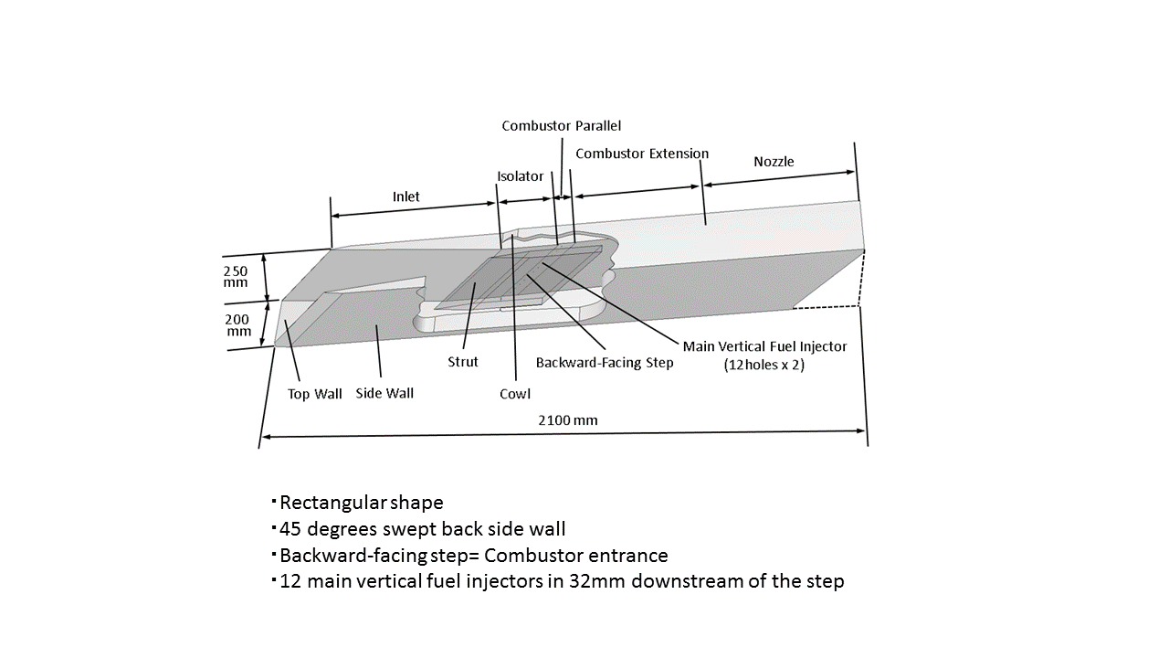
Fig.1: Outline of scramjet engine tested. The engine is set upside-down on the test bed, and 5/5-hieght strut is equipped.
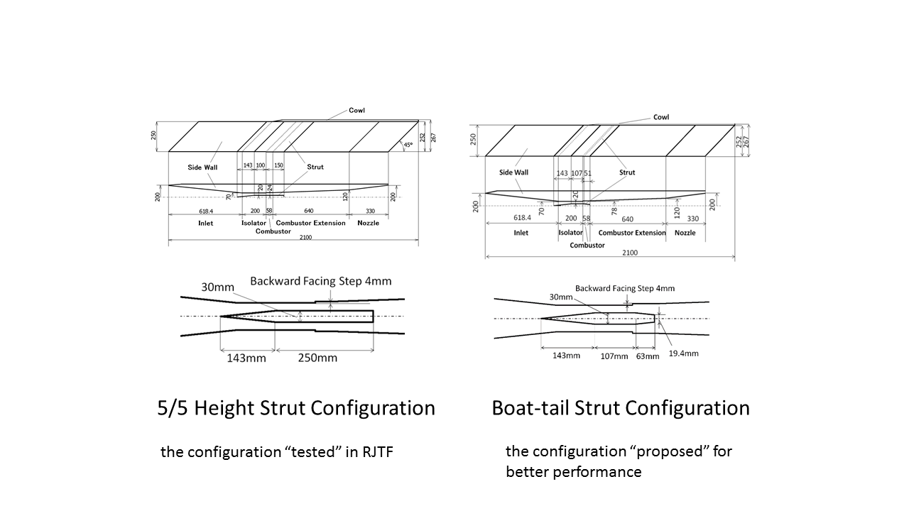
Fig.2: Two types of strut for CFD comparison. a) 5/5H-Strut configuration is used in engine test, and b) the Boat-tail Strut configuration is an improved one designed as a virtual configuration. (unit:mm)
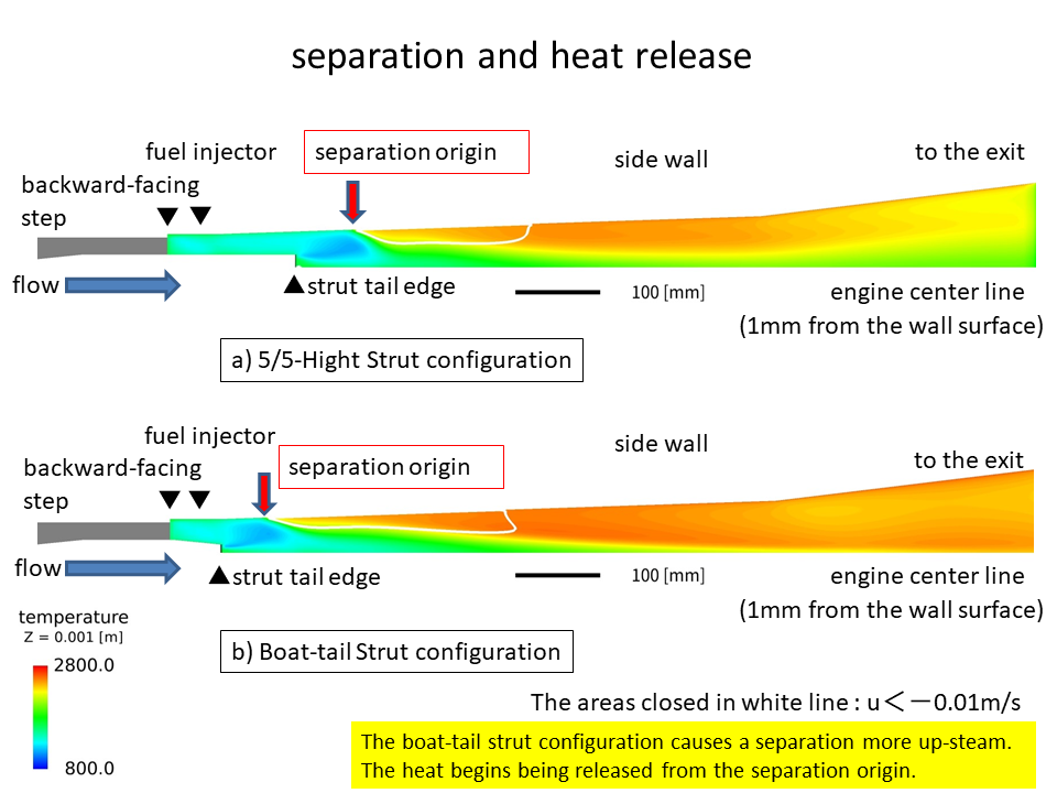
Fig.3: Separation point and high temperature. The separation region is enclosed with white line. The color indicates the temperature.
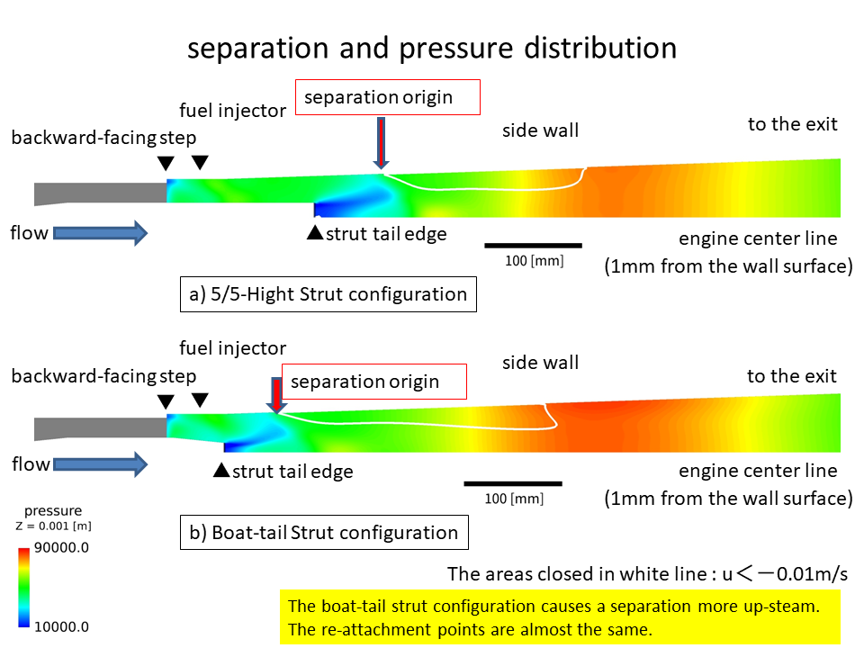
Fig.4: Separation point and pressure distribution. The separation region is enclosed with white line. The color indicates the pressure.
Publications
- Non peer-reviewed papers
SATO Shigeru, FUKUI Masaaki, MUNAKATA Toshihiko, WATANABE Takahiro and TAKAHASHI Masaharu,
Trial for Performance Improvement of Scramjet Engine
―Flow Separation and Fuel Equivalence Ratio Distribution Proceedings of Fluid Dynamics Conference/Aerospace Numerical Simulation Symposium 2020 Online,JAXA Special Publication,JAXA-SP-20-008,March 2021, 2021, JAXA(in Japanese).
- Oral Presentations
1)SATO Shigeru, FUKUI Masaaki, MUNAKATA Toshihiko, WATANABE Takahiro and TAKAHASHI Masaharu,
An Influence of Scramjet Engine Internal Flow Separation on Combustion Performance
―Shock Waves and Fuel Equivalence Ratio, Symposium on Shock Waves in Japan, Mar 03-05 2021, on the Web(in Japanese).
2)SATO Shigeru, FUKUI Masaaki, MUNAKATA Toshihiko, WATANABE Takahiro and TAKAHASHI Masaharu,
Trial for Performance Improvement of Scramjet Engine ― Flow Separation and Fuel Equivalence Ratio Distribution, Fluid Dynamics Conference/Aerospace Numerical Simulation Symposium 2020 Online, Sep.28-30, on the Web(in Japanese).
Usage of JSS
Computational Information
- Process Parallelization Methods: It depends on FLUENT
- Thread Parallelization Methods: It depends on FLUENT
- Number of Processes: 4 - 8
- Elapsed Time per Case: 1680 Hour(s)
Resources Used(JSS2)
Fraction of Usage in Total Resources*1(%): 0.00
Details
Please refer to System Configuration of JSS2 for the system configuration and major specifications of JSS2.
| System Name | Amount of Core Time(core x hours) | Fraction of Usage*2(%) |
|---|---|---|
| SORA-MA | 0.00 | 0.00 |
| SORA-PP | 979.93 | 0.01 |
| SORA-LM | 0.00 | 0.00 |
| SORA-TPP | 0.00 | 0.00 |
| File System Name | Storage Assigned(GiB) | Fraction of Usage*2(%) |
|---|---|---|
| /home | 19.83 | 0.02 |
| /data | 200.82 | 0.00 |
| /ltmp | 1,534.60 | 0.13 |
| Archiver Name | Storage Used(TiB) | Fraction of Usage*2(%) |
|---|---|---|
| J-SPACE | 0.87 | 0.03 |
*1: Fraction of Usage in Total Resources: Weighted average of three resource types (Computing, File System, and Archiver).
*2: Fraction of Usage:Percentage of usage relative to each resource used in one year.
Resources Used(JSS3)
Fraction of Usage in Total Resources*1(%): 0.00
Details
Please refer to System Configuration of JSS3 for the system configuration and major specifications of JSS3.
| System Name | Amount of Core Time(core x hours) | Fraction of Usage*2(%) |
|---|---|---|
| TOKI-SORA | 0.00 | 0.00 |
| TOKI-RURI | 0.00 | 0.00 |
| TOKI-TRURI | 0.00 | 0.00 |
| File System Name | Storage Assigned(GiB) | Fraction of Usage*2(%) |
|---|---|---|
| /home | 25.38 | 0.02 |
| /data | 256.54 | 0.00 |
| /ssd | 109.67 | 0.06 |
| Archiver Name | Storage Used(TiB) | Fraction of Usage*2(%) |
|---|---|---|
| J-SPACE | 0.87 | 0.03 |
*1: Fraction of Usage in Total Resources: Weighted average of three resource types (Computing, File System, and Archiver).
*2: Fraction of Usage:Percentage of usage relative to each resource used in one year.
JAXA Supercomputer System Annual Report April 2020-March 2021