
Large-eddy simulation of a full-scale liquid rocket engine combustor
JAXA Supercomputer System Annual Report April 2020-March 2021
Report Number: R20EFHC0303
Subject Category: Common Business
- Responsible Representative: Takanori Haga, Research Engineer, Research and Development Directorate, Research Unit III
- Contact Information: Takanori Haga, Research and Development Directorate, Research Unit III(haga.takanori@jaxa.jp)
- Members: Takanori Haga, Kiyoshi Kumahata, Seiji Tsutsumi, Hiroyuki Ito
Abstract
In this work, we focus on the spatial distribution and time fluctuation of the wall heat flux assumed in the full-scale engine, and perform a complete three-dimensional large-eddy simulation (LES). The purpose of this work is to acquire knowledge that cannot be obtained by conventional simplified analysis (single or several injectors, cake-cut shape assuming symmetry in the circumferential direction). The analysis target is a full-scale combustor (528 injectors) of the LE-X engine, and a large-scale combustion LES is performed using an efficient tabulated chemistry (flamelet) model. Such a LES of 100 or more injectors has never been reported, and it will be possible for the first time by combining the computing performance of the JAXA's new supercomputer JSS3 with the next-generation large-scale and high-speed solver LS-FLOW-HO developed in JAXA.
Reference URL
N/A
Reasons and benefits of using JAXA Supercomputer System
To perform LES for full-scale combustors (500 or more injectors), it is necessary to use at least billions to tens of billions of computational points and to integrate in time on the order of one million steps. Therefore, the use of computational resources which is the majority of JSS3 is essential.
Achievements of the Year
1. Objective
In full-scale combustor and engine tests, the hazard events of oscillating combustion and melting are the risks of increased development costs. In the LE-9 engine, fatigue fracture surfaces were confirmed in the apertural area of the combustion chamber inner wall, which revealed the difficulty of predicting the full-scale effect, unsteady state, and thermal-fluid coupling in advance.
In this work, we focus on the spatial distribution and time fluctuation of the wall heat flux assumed in the full-scale engine, and perform a complete three-dimensional large-eddy simulation (LES). The purpose of this work is to acquire knowledge that cannot be obtained by conventional simplified analysis (single or several injectors, cake-cut shape assuming symmetry in the circumferential direction). The analysis target is a full-scale combustor (528 injectors) of the LE-X engine, and a large-scale combustion LES is performed using an efficient tabulated chemistry (flamelet) model. Such a LES of 100 or more injectors has never been reported, and it will be possible for the first time by combining the computing performance of the JAXA's new supercomputer JSS3 with the next-generation large-scale and high-speed solver LS-FLOW-HO developed in JAXA.
2. Numerical methods and preparation
2.1 LS-FLOW-HO
The flux reconstruction (FR) method, which is a high-order unstructured grid method, is used to discretize the governing equations. Since each grid cell has the degrees of freedom required for high-order accuracy, it is possible to use the cache by taking advantage of the locality of the data, and since only surface data is required for inter-cell communication, the amount of communication between processes is reduced. As a result, high running performance and parallel efficiency can be expected. Since the degrees of freedom in the cell are stored in the memory when the calculation is executed, there is an advantage that the data size of the computational grid can be reduced to several tens to one hundredth compared to the conventional methods. The JAXA in-house combustion LES solver LS-FLOW-HO has been developed based on the FR method and used in this work.
A Flamelet Progress Variable (FPV) model is used as the combustion model. To consider the physical properties of cryogenic liquid oxygen (LOX), the SRK equation of state and the Chung's transport coefficients model are used. The Chung's model is not correlated well at high temperatures, and the transport coefficients of the mixture considered represented in the FPV lookup table may be a non-physical value, so it is applied only to LOX. The transport coefficients of chemical species other than LOX was evaluated by the CHEMKIN database, and the transport coefficients of the mixture was evaluated by the Wilke model. A positivity preserving limiter is applied to the reconstructed solution polynomials to suppress numerical oscillations at the LOX interface where the density ratio exceeds 100. During the preparation period of this challenge, to validate the solver in which these high-pressure combustion models are introduced, a LES of LOX / GH2 coaxial jet flame (DLR P8) under supercritical pressure (6 MPa) was performed. It was confirmed that a reasonable flame shape and shear layer velocity distribution were obtained by comparing with the LES results in the literature.
2.2 Computational grids of full-scale combustor
The target of this full-scale analysis is one of the test cases of the LE-X engine. The overset grid method is adopted to consider all 528 coaxial injectors. Since there are three types of injectors with different lengths, three computational grids (hexahedral cell) were generated in consideration of the development of the shear layer and the mixing region in the combustor. By copying 528 of these grids and translating them to each element position, they were overlapped onto the separately generated combustor grid (including from the injection faceplate to the CV nozzle exit). The domain size (cylindrical diameter) of injector was adjusted in advance so that the grids of each injector did not overlap in the combustor, and the boundary surface was retained to be used as the overset surface. In the combustor grid, the grid cells enclosed in all the injector grids were deleted, and a hole-cut was performed as a pre-process to create an overset surface that communicates with the injector side.
Figure 1 shows the combustor grid after the hole-cut. The number of cells of the injector grid and the combustor grid (after hole-cut) is about 340,000 and 40.73 million, respectively, and the total number of cells is about 218.26 million. Note that the number of grid cells is smaller than that of the conventional method because the degrees of freedom in the cell (27 points / cell for the p2 scheme) is used. The total number of computational points (p2 scheme) is 5,896 million. Regarding the grid generation, to represent the cylindrical shape and curvature of the injector and combustor with a small number of cells, the grid cells near the wall were set to the second-order hexahedral elements. By reducing the number of cells, the pre-processing time for large-scale hole-cut can be significantly shortened, but since the present tool does not support process parallelism, it took about 5 hours to process 528 cells using 1 node (36 cores, 192 GiB) of the TOKI-RURI system.
2.3 Verification for each component
As a preparation for full-scale analysis, the computational grid was divided into each component and computations were performed to confirm that there were no problems with numerical stability. Specifically, computations were performed for three cases: a) single injector grid, b) overset grid consists of a single injector and the combustor (partial), and c) single combustor grid. The pressure and temperature of the burnt gas were given to the boundary conditions of the overset surface of the single grid cases a) and c). Figure 2 shows the results of case a), and Fig. 3 shows the results of cases b) and c). In all of the three cases, a part of the computational domain of the combustor was cut out, and in cases a) and c), when a long physical time was computed, instability of the flow field was observed in the vicinity of the cut out boundary surface. It is considered that this is due to the inconsistency of the boundary conditions, and since stable calculation can be performed up to about 1 [ms] where the flow field develops to some extent, it was judged that it would not be manifested by the full-scale analysis.
2.4 Preparing the restart solution
To shorten the computational time of the full-scale analysis, a small-scale computation was performed until the turbulent flame developed in the single injector grid, and the field data was used as the restart solution of the full-scale analysis. For three cases with different element lengths, the preprocessing time was shortened by increasing the number of domain divisions and the number of computer nodes. Using 128 TOKI-SORA nodes per case, it took about one day to analyze 1 [ms]. Since the restart data does not include the position coordinates, it is sufficient to copy the results of 3 cases for 528 lines according to the injector position and length, but mapping is required because the number of divisions is different from the single injector grid for full-scale analysis. The mapped restart data was prepared by extending the in-house preprocessing tool.
2.5 High-speed tuning
In parallel with the above preparations, high-speed tuning of LS-FLOW-HO was performed on TOKI-SORA (FX 1000). High-cost routines were identified by the profiler, and the top two routines were speeded up. These are the routine that calculates the Riemann flux at the cell interface and the routine that includes Newton iterations for temperature calculation, but the details of tuning are omitted in this paper. As a result of tuning, about twice the speed was obtained in the test case with a single node. The running performance is about 4% of the peak. The computation time of the single injector (DLR P8) used for the validation was about 1 day per case using the TOKI-SORA 320 node, which was about 15 times faster than the conventional solver LS-FLOW. It should be noted that LS-FLOW has a problem in the stability of the implicit method in high-pressure combustion cases, and the fact that the time step cannot be taken large is a factor in the increase in computational time.
3. Full-scale combustor LES
The analysis conditions correspond to a test case with a combustion pressure of 8.2 [MPa] and a mixing ratio of 6.4 for the LE-X engine. The temperature and mass flow rate of the propellant were given to the inflow conditions of the injector. For the boundary conditions of the combustor wall surface, the temperature distribution obtained by a thermal-fluid coupled analysis (steady RANS) of the combustion gas flow, solid heat conduction, and coolant flow was given. The nozzle outlet is a supersonic outflow condition. A pre-prepared restart solution was given as the initial condition. For the full-scale LES, 2880 nodes, which is half the total number of JSS3 TOKI-SORA nodes, were used. Four processes were set up on each node (12 threads per process), and 11520 processes in total were computed. The wall-clock time per step is about 1.03 seconds, and about 1.17 million steps can be executed in the occupancy period of 2 weeks. Since the explicit method is used for time integration, the time step is 3.0 e-9 [s / step], and the physical time that can be analyzed is about 3.5 [ms]. This is not always sufficient to obtain the time averaged flowfield, but it is clearly insufficient to reproduce the transient state, and the use of the restart solution described above is essential. In addition, this wall-clock time is about 1.5 times longer than the predicted value based on the small-scale single injector case, and it is possible that communication between overset grids affects the performance of large-scale parallelism.
Figure 4 shows the flowfield immediately after the start of the computation. After this (after about 30,000 steps), the pressure and temperature became non-physical values near the recess of the injector, and the calculation failed. As a stabilization measure, we tried applying a low-pass filter to remove high-frequency components and recomputing the restart solution, but we could not suppress the instability and unavoidably interrupted the full-scale LES. One of the causes of instability is the lack of resolution and quality of the injector grid. In the case of a single injector, we observed that the flame surface moved to a region where the resolution is insufficient depending on how the initial conditions are given, and the computation failed. In full-scale LES, the flame surface may have become unstable due to mutual interference of the flowfield of each injector.
4. Achievements and future works
Unfortunately, we could not obtain the originally planned LES results in this challenge due to the instability of the computation. However, we accelerated the validation of each physical model for high-pressure combustion newly introduced in LS-FLOW-HO and succeeded in computing the single-injector benchmark problem. As far as the authors know, there is no other example of high-pressure combustion LES of LOX / GH2 by the FR method and similar method, and the details of the proposed method will be submitted in an academic journal. We also confirmed that we established a pre-processing and post-processing method for large-scale LES of complex geometry using the overset grid method, and that large-scale parallel computing using up to 2880 nodes could be performed. The extended physical models and speedup of LS-FLOW-HO acquired by this challenge are great achievements that can be used for single injector sensitivity analysis and subscale combustor analysis.
Currently, we are investigating the cause of instability, focusing on the single injector. As the next step, we will confirm the robustness of the solver by conducting a subscale LES of multiple injectors or cake-cut shape assuming symmetry of injector arrangement, and then prepare for the full-scale LES.
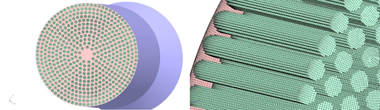
Fig.1: Boundary surfaces of the full-scale combustor after hole-cut (left). Overset boundary surfaces generated by hole-cut (right).
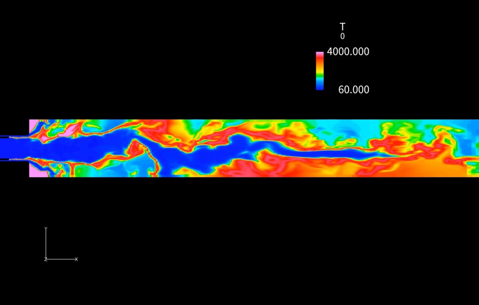
Fig.2: Result of Case a) single injector grid (instantaneous flowfield).
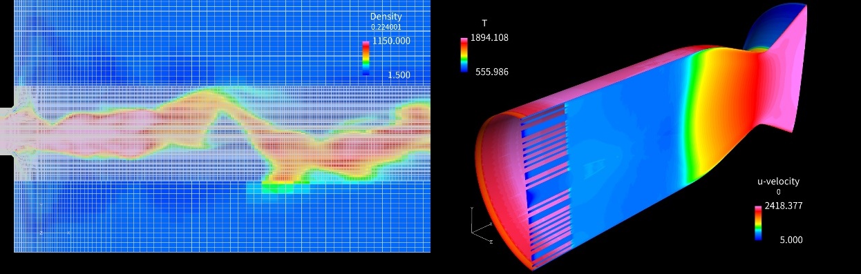
Fig.3: Result of Case b) overset grid of single injector and a part of combustor (left, instantaneous flowfield). Result of Case c) single combustor grid (right, in a transient state from the initial condition).
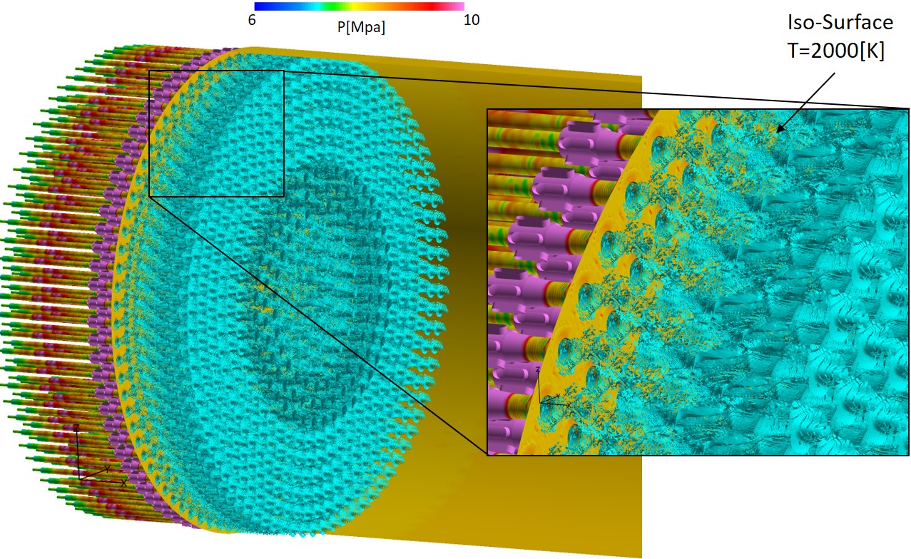
Fig.4: Result of full-scale LES (instantaneous flowfield immediately after restart).
Publications
N/A
Usage of JSS
Computational Information
- Process Parallelization Methods: MPI
- Thread Parallelization Methods: OpenMP
- Number of Processes: 11520
- Elapsed Time per Case: 336 Hour(s)
Resources Used(JSS2)
Fraction of Usage in Total Resources*1(%): 0.00
Details
Please refer to System Configuration of JSS2 for the system configuration and major specifications of JSS2.
| System Name | Amount of Core Time(core x hours) | Fraction of Usage*2(%) |
|---|---|---|
| SORA-MA | 0.00 | 0.00 |
| SORA-PP | 0.00 | 0.00 |
| SORA-LM | 0.00 | 0.00 |
| SORA-TPP | 0.00 | 0.00 |
| File System Name | Storage Assigned(GiB) | Fraction of Usage*2(%) |
|---|---|---|
| /home | 236.64 | 0.22 |
| /data | 11,897.41 | 0.23 |
| /ltmp | 626.63 | 0.05 |
| Archiver Name | Storage Used(TiB) | Fraction of Usage*2(%) |
|---|---|---|
| J-SPACE | 50.28 | 1.66 |
*1: Fraction of Usage in Total Resources: Weighted average of three resource types (Computing, File System, and Archiver).
*2: Fraction of Usage:Percentage of usage relative to each resource used in one year.
Resources Used(JSS3)
Fraction of Usage in Total Resources*1(%): 7.52
Details
Please refer to System Configuration of JSS3 for the system configuration and major specifications of JSS3.
| System Name | Amount of Core Time(core x hours) | Fraction of Usage*2(%) |
|---|---|---|
| TOKI-SORA | 40,972,445.31 | 8.81 |
| TOKI-RURI | 103,790.33 | 0.59 |
| TOKI-TRURI | 0.00 | 0.00 |
| File System Name | Storage Assigned(GiB) | Fraction of Usage*2(%) |
|---|---|---|
| /home | 403.12 | 0.28 |
| /data | 135,258.31 | 2.27 |
| /ssd | 444.30 | 0.23 |
| Archiver Name | Storage Used(TiB) | Fraction of Usage*2(%) |
|---|---|---|
| J-SPACE | 50.28 | 1.66 |
*1: Fraction of Usage in Total Resources: Weighted average of three resource types (Computing, File System, and Archiver).
*2: Fraction of Usage:Percentage of usage relative to each resource used in one year.
JAXA Supercomputer System Annual Report April 2020-March 2021