
Feedback Control of Flow Separation Using DBD Plasma Actuator
JAXA Supercomputer System Annual Report April 2020-March 2021
Report Number: R20EACA26
Subject Category: JSS Inter-University Research
- Responsible Representative: Kengo Asada, Assistant Professor, Department of Information and Computer Technology, Faculty of Engineering, Tokyo University of Science
- Contact Information: Kengo Asada(asada@rs.tus.ac.jp)
- Members: Kengo Asada, Takuto Ogawa
Abstract
The project develops flow control technic by using dielectric barrier discharge (DBD) plasma actuator to establish high efficient and robust vehicle systems such as rockets, aircrafts, and motor vehicles. We propose and demonstrate feedback control methods to adapt unsteady flows over the vehicles through a series of high-fidelity unsteady simulations.
Reference URL
N/A
Reasons and benefits of using JAXA Supercomputer System
To perform large-scale three-dimensional unsteady flow simulations using the compressible fluid solver LANS3D, which has a wealth of computational achievements with a JAXA supercomputer system.
Achievements of the Year
This year, we conducted a performance verification of the feedback control model for the DBD plasma actuator (PA), whose effect has been confirmed so far in the present project by performing the high-fidelity large-eddy simulations of the flow over the NACA0015 airfoil at Reynolds number 63,000. The considering feedback model (Fig. 1) drives PA located in the vicinity of the leading edge according to the passing of vortices above a pressure sensor on the airfoil's upper side. An abrupt pressure decrease detects the passing of vortices compared to a moving-averaged pressure value. In the present model, the time range of the moving average is varied according to FFT analysis. So far, we have shown the effectiveness of the feedback control model at 12 degrees near the stall angle of attack in the flow around the NACA0015 wing. Last year, we confirmed that the control model has a certain effect on controlling separation bubbles near the leading edge even for the flow at the cruising angle of attack (4, 6, 8 degrees). This year, we performed the simulations of the flow at a lower angle of attack (2 degrees) and compared the aerodynamic performance using the feedback control model with that using the existing control method and that of Ishii airfoil, which shows high aerodynamic performance at low angles of attack.
Figure 2 shows the lift and drag ratios (L/Ds) obtained by the simulations of the flows controlled by the feedback control model (FB) and the burst-mode actuation (Burst), the flow without control (Baseline), and the flow around Ishii airfoil (ISHII). The burst-mode actuation and Ishii airfoil are known to provide high aerodynamic performances at high angles of attack and low Reynolds numbers, respectively. The feedback control obtains a lift-drag ratio equal to or higher than that of burst control, an existing control method, at angles of attack of 4, 6, and 8 degrees. On the other hand, at 2 degrees, the lift-drag ratio is lower than that of the non-control case, and it can be said that there is room for improvement in the feedback control model. To clarify the cause of the low performance of the feedback control at angles of attack of 2 degrees, we investigated the flow field.
Figure 3 shows the feedback control model at an angle of attack of 2 degrees and the pressure distribution on the baseline case's airfoil surface. By applying the feedback control model, the pressure increases on the airfoil's suction side and decreases on the pressure side. Therefore, the lift generated by these differences is greatly reduced. The drag is also slightly reduced, but the lift-drag ratio is lower than in the baseline case because the lift is more reduced.
Figure 4 shows instantaneous flow fields of the feedback control case and the baseline case at the angle of attack of 2 degrees. The isosurface is the second invariant of the velocity gradient tensor colored by the velocity in the chordwise direction, showing a vortex structure. In uncontrolled flow (the baseline case), large-scale laminar flow separation bubbles are generated from the front edge to the trailing edge. This separation bubble maintains a low airfoil surface pressure over a wide area on the upper surface (suction side) of the airfoil. On the other hand, two-dimensional vortices are generated in the feedback control case by driving the PA and flows downstream. These vortices have the function of suppressing laminar flow separation and, as a result, recovering the pressure on the upper surface of the airfoil. In this way, at the angle of attack of 2 degrees, the flow separation is suppressed by applying the present feedback control model, but the lift obtained by the separation bubble is significantly reduced, resulting in decreased lift-drag ratio.
In the future, it will be possible to maintain high wing performance over a wider angle of attack by improving the feedback control method, such as weakening the flow separation control effect under the intended conditions.
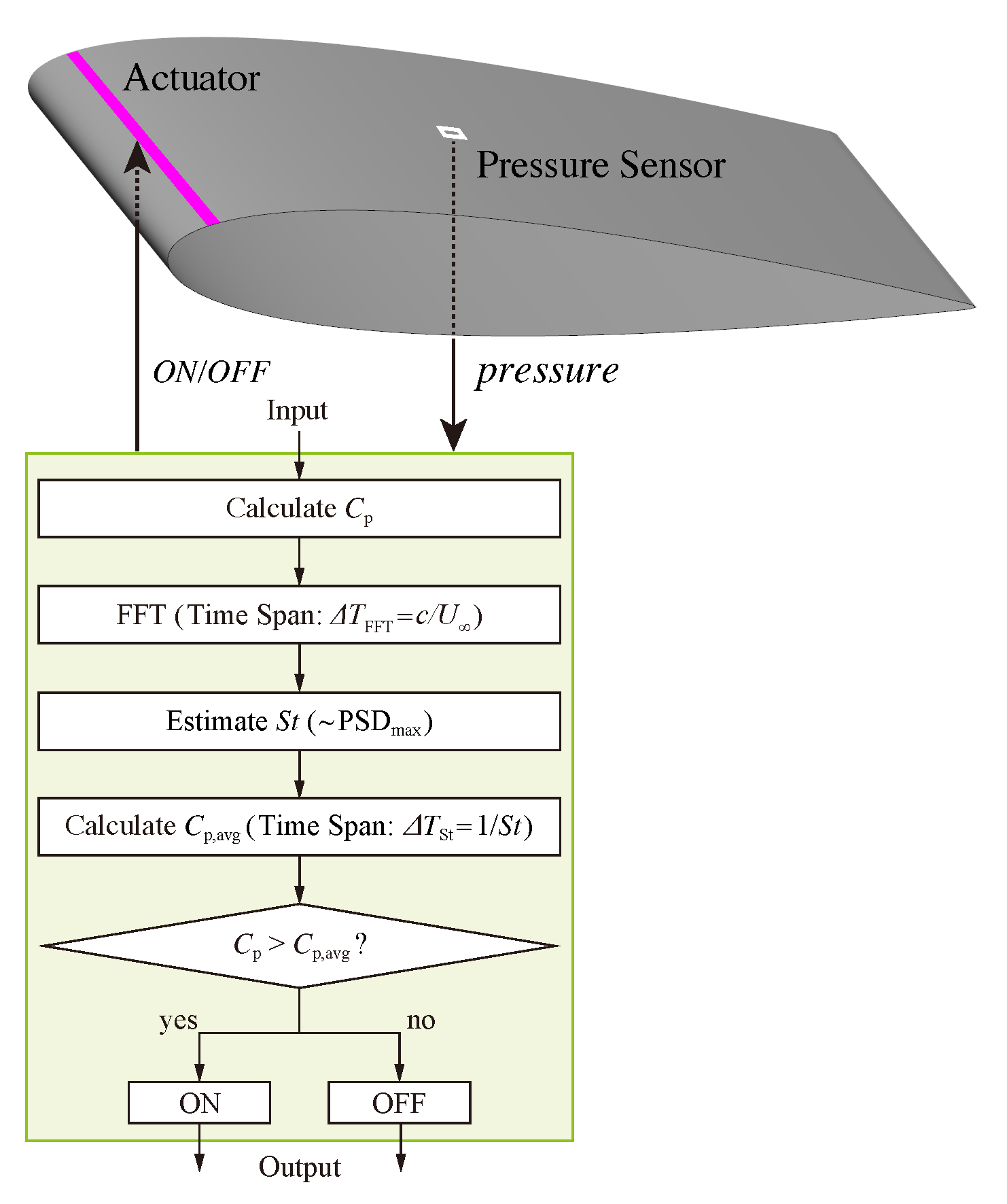
Fig.1: Proposed feedback control model for airfoil flow separation.
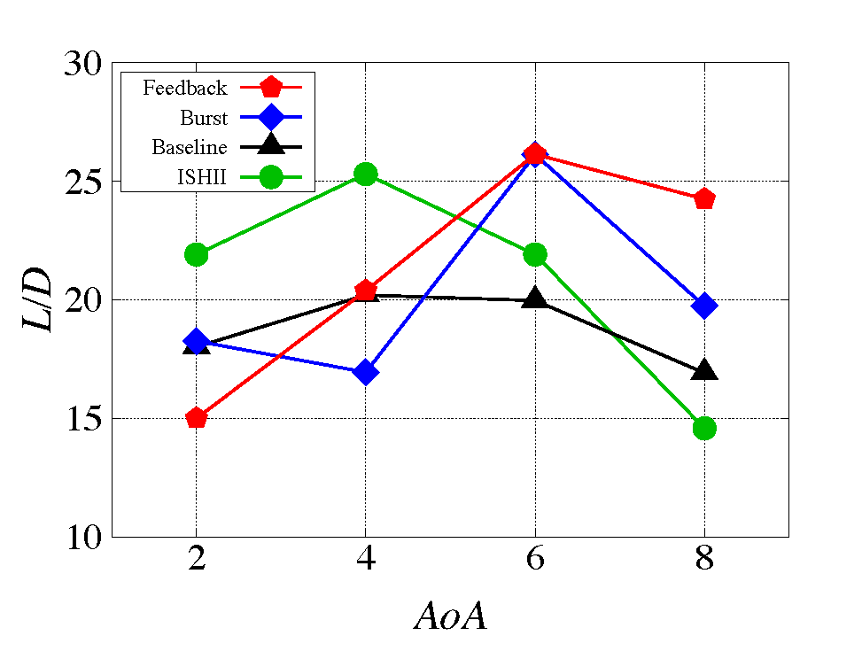
Fig.2: Lift and drag ratio (L/D) at angles of attack of 2 to 8 degrees.
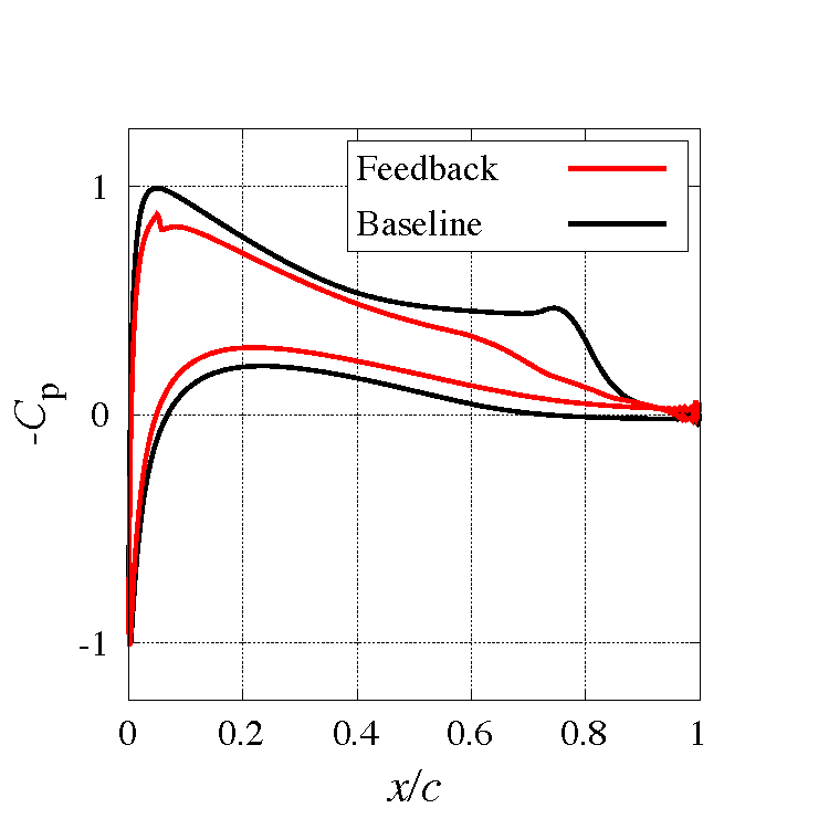
Fig.3: Distributions of the pressure coefficient of the feedback control case and the baseline case around the airfoil at the angle of attack of 2 degrees.
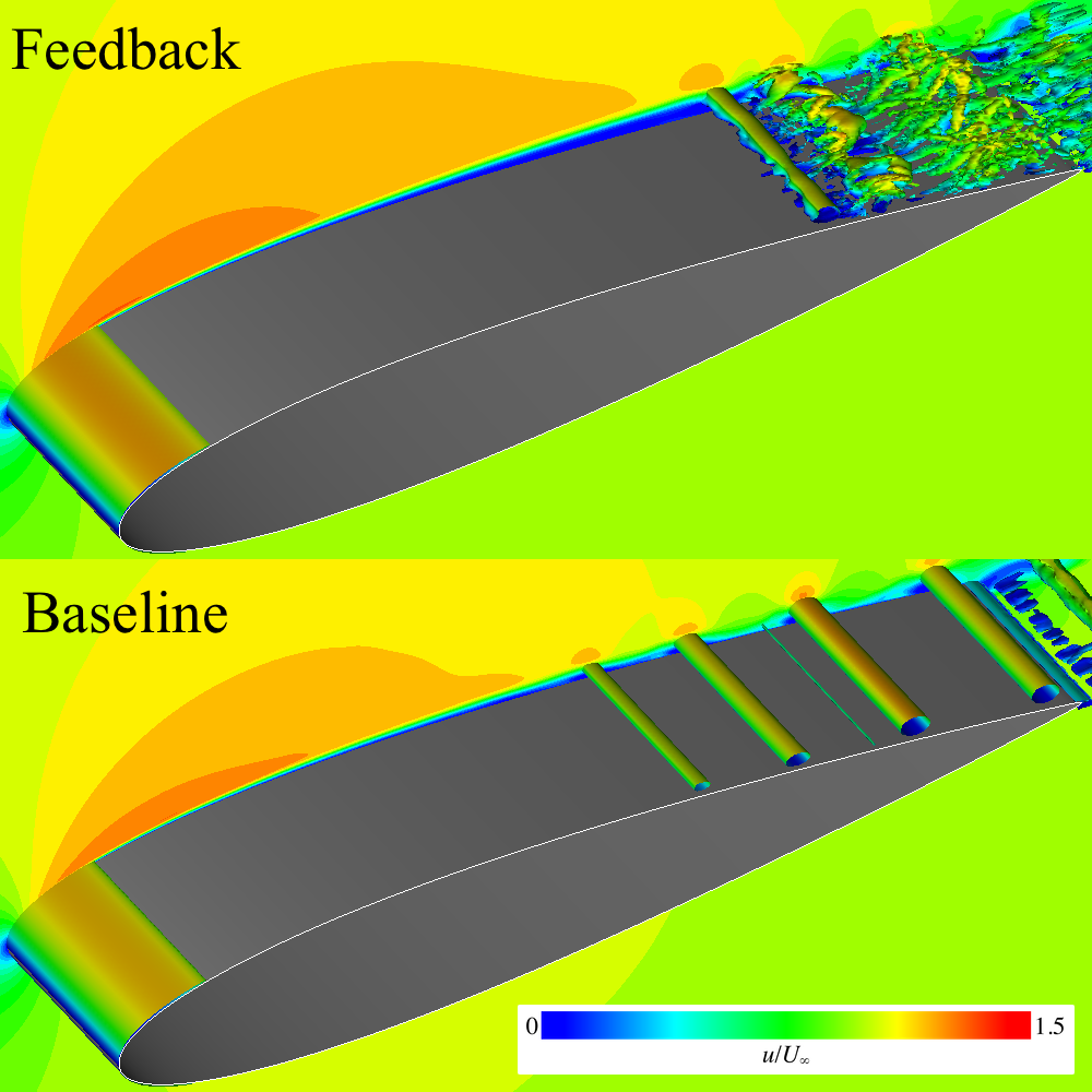
Fig.4: Instantaneous flow fields of the feedback control case and the baseline case at the angle of attack of 2 degrees. The isosurface is Q-criterion colored with the chordwise velocity.
Publications
N/A
Usage of JSS
Computational Information
- Process Parallelization Methods: MPI
- Thread Parallelization Methods: OpenMP
- Number of Processes: 79
- Elapsed Time per Case: 30 Hour(s)
Resources Used(JSS2)
Fraction of Usage in Total Resources*1(%): 0.03
Details
Please refer to System Configuration of JSS2 for the system configuration and major specifications of JSS2.
| System Name | Amount of Core Time(core x hours) | Fraction of Usage*2(%) |
|---|---|---|
| SORA-MA | 133,794.84 | 0.03 |
| SORA-PP | 0.00 | 0.00 |
| SORA-LM | 0.00 | 0.00 |
| SORA-TPP | 0.00 | 0.00 |
| File System Name | Storage Assigned(GiB) | Fraction of Usage*2(%) |
|---|---|---|
| /home | 52.45 | 0.05 |
| /data | 15,315.10 | 0.30 |
| /ltmp | 2,929.69 | 0.25 |
| Archiver Name | Storage Used(TiB) | Fraction of Usage*2(%) |
|---|---|---|
| J-SPACE | 0.00 | 0.00 |
*1: Fraction of Usage in Total Resources: Weighted average of three resource types (Computing, File System, and Archiver).
*2: Fraction of Usage:Percentage of usage relative to each resource used in one year.
Resources Used(JSS3)
Fraction of Usage in Total Resources*1(%): 0.01
Details
Please refer to System Configuration of JSS3 for the system configuration and major specifications of JSS3.
| System Name | Amount of Core Time(core x hours) | Fraction of Usage*2(%) |
|---|---|---|
| TOKI-SORA | 0.00 | 0.00 |
| TOKI-RURI | 0.00 | 0.00 |
| TOKI-TRURI | 0.00 | 0.00 |
| File System Name | Storage Assigned(GiB) | Fraction of Usage*2(%) |
|---|---|---|
| /home | 57.22 | 0.04 |
| /data | 15,981.76 | 0.27 |
| /ssd | 190.73 | 0.10 |
| Archiver Name | Storage Used(TiB) | Fraction of Usage*2(%) |
|---|---|---|
| J-SPACE | 0.00 | 0.00 |
*1: Fraction of Usage in Total Resources: Weighted average of three resource types (Computing, File System, and Archiver).
*2: Fraction of Usage:Percentage of usage relative to each resource used in one year.
JAXA Supercomputer System Annual Report April 2020-March 2021